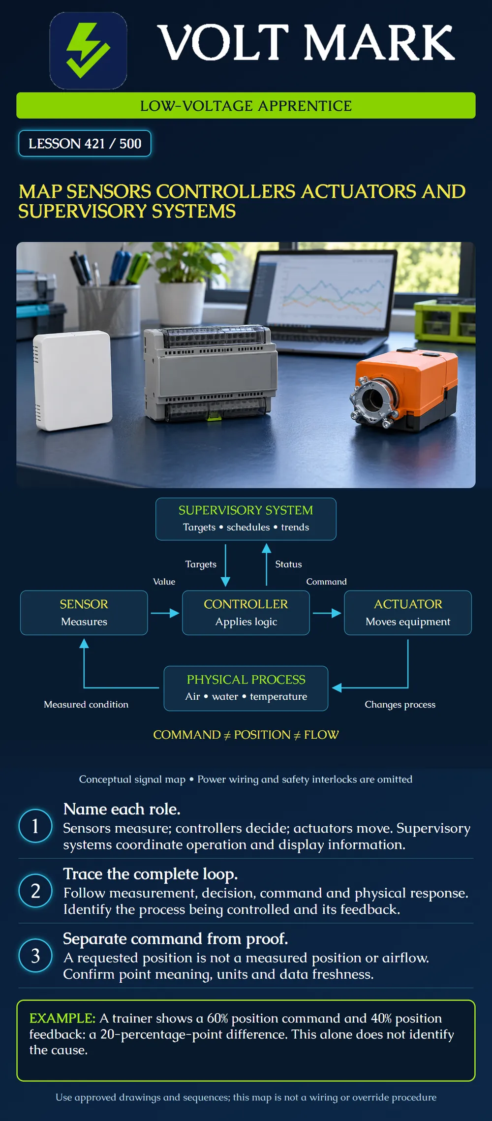
Identify four control-system roles and trace a measurement through a local control loop. Distinguish supervisory information from field action, and distinguish a command from evidence of the physical result.
This is a conceptual low-voltage controls lesson. It is not a wiring diagram, controller program, commissioning sequence or authorization to override equipment. The poster omits power wiring, safety interlocks, auxiliary feedback and many network details so the main information path is readable. Actual equipment may include line voltage, moving machinery or other hazards even when its control signals are low voltage.
A sensor measures a physical condition. A controller receives information and applies its programmed logic or control algorithm. An actuator converts a control request into mechanical action. A supervisory system coordinates higher-level operation and presents information to operators. One physical product can contain several roles; a network thermostat, for example, need not be only a sensor.
NIST's control-loop definition identifies measurement, controller decisions, actuator action and renewed measurement of the changing process. Its HVAC controls technical note distinguishes local regulation from supervisory decisions. Belimo's actuator guide describes control inputs and position-feedback outputs. These sources support the architecture concepts, not a universal terminal assignment or sequence.
An instructor gives the apprentice a fictional air-control trainer with these identifiers: S-1: airflow sensor. C-1: local controller. A-1: damper actuator. P-1: the duct airflow affected by the damper.
Write the role next to each identifier. Then mark the arrows: S-1 to C-1 is a measured value; C-1 to A-1 is a command; A-1 changes P-1 mechanically; P-1 is measured by S-1. SUP-1 exchanges permitted targets and status with C-1.
This exercise is not a prescription for actual airflow-control logic. The instructor supplies the approved sequence and point definitions for any later trainer activity. A real installation could use a different sensor, actuator arrangement, network architecture or control method.
For every point in the fictional map, record its identifier, source, destination, role and engineering unit. Include its signal or network representation only when that information is supplied. Do not guess that every value is a 0–10 V signal, that every controller input is compatible, or that a network point maps directly to a physical terminal.
A point named “damper” is ambiguous. It might represent a requested percentage, an internally reported position or a separate end switch. Labeling the role prevents the reader from confusing these different pieces of evidence. A useful map distinguishes a command point from a feedback point.
The NIST technical note describes local control regulating an individual process and supervisory control making broader decisions, such as selecting targets. A building interface can also present historical trends. The specific arrangement depends on the installed design.
For the fictional trainer, ask the instructor where C-1's logic executes and where its target originates. Ask what the documented behavior is if the supervisory connection is unavailable. Do not answer by assumption: some local functions may continue while dependencies or stale data affect other functions. This lesson provides no universal network-loss or fail-safe behavior.
Belimo's guide shows that electronic actuator control signals and position feedback serve different purposes. Position feedback describes the actuator's reported position according to the product's design. The guide also explains that damper position and airflow do not have a universal linear relationship.
For the original exercise, SUP-1 shows a 60% position command and a 40% position-feedback value. Their numerical difference is: 60% − 40% = 20 percentage points.
This is not a statement that airflow is 20% low. It is not a relative-percent-error calculation, and it is not enough to diagnose a failed actuator. Before drawing conclusions, the learner needs the point definitions, timestamps, scaling and expected response time supplied by the instructor.
The two values could have been captured at different times. The actuator might still be moving. The feedback might describe something different from what its label suggests. A mechanical issue is another possibility, but the arithmetic alone cannot distinguish these possibilities. Record the observation and the missing information without claiming a cause.
The value of a role map is that it gives each observation a place. If the displayed measurement appears inconsistent, the team knows which sensor and data path the value belongs to. If the requested action and reported result differ, the command path and feedback definition are visible.
This lesson stops at that identification task. Testing voltages, forcing outputs, changing program logic and moving dampers belong to later authorized procedures with qualified supervision. Do not bypass an interlock to make the diagram's arrows appear to work.
On the fictional map, add a dashed optional arrow from A-1 back to C-1 labeled “position feedback, if provided.” Explain why this differs from S-1's airflow measurement. Then add a note identifying where the actual power supply information would be found: the approved equipment wiring documentation, not this conceptual diagram.
Q1. Which role measures the physical condition?
NIST CSRC, Control Loop glossary, referencing SP 800-82 Rev. 3: https://csrc.nist.gov/glossary/term/control_loop NIST TN 2178, Baseline Control Systems in the Intelligent Building Agents Laboratory, sections 1.4–1.5: https://tsapps.nist.gov/publication/get_pdf.cfm?pub_id=933128 Belimo Damper Actuator Applications Guide, flow characteristics and electronic actuators: https://www.belimo.com/mam/americas/technical_documents/Support%20material/belimo_damper-applications_guide_en-us.pdf
The diagram, identifiers, exercise and questions are original instructional material. The Belimo guide is used for conceptual distinctions, not universal product ratings or current model installation instructions. No local license scope or nationwide wiring rule is invented.
Mistake: Treating supervisory workstation status as proof of actuator motion. Correction: Trace the command, its feedback source and the measured physical process as separate evidence paths.
Mistake: Reporting 60% command minus 40% position as 20% airflow loss. Correction: State the 20-percentage-point position difference and obtain the independent airflow evidence.
Mistake: Assuming local regulation stops whenever the supervisory connection fails. Correction: Locate the logic and its documented network dependencies before predicting loss-of-connection behavior.
Texas journeyman, 15 questions, scored by topic against the 70% mark. No card, and no account needed to start.
Free study material for low-voltage apprentices. This is a national foundation course: requirements differ by state and by local jurisdiction, and a practice that is common in one place is not a rule everywhere. Nothing here is a licence, a certification, or authority to work unsupervised, and completing it does not count as apprenticeship hours or continuing-education credit. Check the codes adopted where you are working, the licensing authority for that work, and your employer's safety programme. VoltMark is not affiliated with, endorsed by, or sponsored by NFPA, OSHA, NICET, BICSI, FOA, or any state or local licensing authority.

Electrician licensing exam prep: practice questions, timed exam simulations, and step-by-step help finding every answer in the NEC.