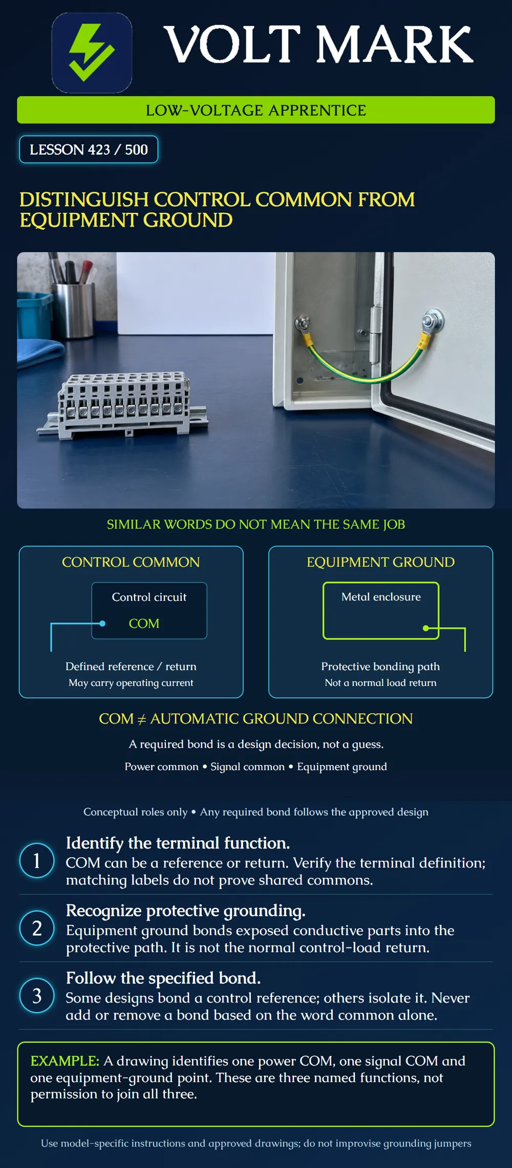
Distinguish a circuit common from an equipment grounding connection. Read terminal definitions and an approved diagram before deciding whether two points are intended to be connected. Explain why a label, wire color or apparent electrical continuity does not by itself authorize a new bond.
This is a paper-diagram lesson for low-voltage controls. It is not permission to install or remove grounding connections, disconnect protective conductors or probe energized equipment. Actual enclosures can contain line voltage even when their control circuits use low voltage. Work within training, authorization and the applicable electrical safety procedure.
Common describes a reference or shared circuit connection in a particular design. A supply COM can serve as the return side of a control-power circuit. A signal common can provide the reference for a signal. Their exact meaning comes from the model's terminal description and schematic.
Do not assume power COM, analog-input COM and communication reference terminals are all internally connected. They may be shared, isolated or related through circuitry. The same lettering on different products does not establish the same electrical arrangement. A relay contact marked COM is another use of the word: it identifies the common contact of the switching arrangement, not automatically a power return or equipment ground.
The equipment grounding function concerns conductive equipment parts and the protective fault-current path. OSHA's construction definitions identify the equipment grounding conductor as connecting normally non-current-carrying equipment metal, raceways and enclosures to the specified grounding arrangement. OSHA's grounding guidance also emphasizes continuity and the ability to carry imposed fault current.
This is a different purpose from carrying the intended operating current of a control load. Do not substitute a metal enclosure or protective conductor for a missing control return. Do not remove protective grounding to eliminate a control problem.
Johnson Controls' EasyIO FW-28 Quick Start Guide, power-supply terminal section, identifies HOT and COM power terminals. It states that the controller does not require an earth-ground connection and provides a particular instruction for the situation in which its 24 VAC transformer secondary needs grounding. It also warns about incorrect wiring and notes that transformer lead colors can differ by manufacturer.
That example demonstrates why the exact product matters. It is not a blanket instruction for every controller, transformer or circuit to use the same grounding arrangement. The poster therefore provides no generic jumper, terminal number or bonding location.
An instructor provides an invented device map containing:
EG: the enclosure's equipment-grounding point.
The learner has three named functions. There is no documentation in the exercise showing whether P-COM and S-COM are internally connected, whether either is isolated, or whether a designed bond exists elsewhere. The correct next step is to obtain the missing terminal and grounding documentation from the instructor.
The incorrect conclusion is “all three are common ground, so join them.” The names do not supply the missing circuit information. A missing line in a simplified drawing is also not evidence that the actual design forbids a bond. Identify what is known and what remains unknown.
Now the instructor supplies a second drawing with a specifically identified bond. The learner should record its location and purpose as shown, without adding another connection or deleting the existing one. The exercise is about reading evidence, not altering a trainer or installed system.
Suppose a fictional service note reports continuity between two points. That observation alone does not identify every possible path between them. The path could involve a documented bond, connected equipment or other circuitry. It does not prove that the installer should add a second connection.
Likewise, a voltage reading depends on the points selected and the measurement conditions. A COM label does not mean the terminal is guaranteed to be at zero voltage relative to every other object. No numeric pass/fail threshold is provided here because the lesson does not establish a universal test procedure.
The qualified person uses the actual schematic and an appropriate authorized verification method. An apprentice should report the recorded observation precisely and avoid guessing that a grounding change is the cure.
For each terminal in the instructor's drawing, record the equipment model, terminal label, stated function, documentation reference and documented connection destination. Record uncertainties explicitly. “Reference relationship not established by supplied drawing” is a more useful note than an invented connection.
Keep protective grounding questions distinct from signal-noise questions. An improvised bond can create unintended paths or interfere with operation; removing a required protective connection can compromise protection. Escalate discrepancies to the responsible qualified person while retaining the actual wiring record.
Draw three separate labeled boxes for P-COM, S-COM and EG. Add only the connections shown in the instructor-provided approved diagram. For every line, explain its documented purpose. If the supplied material lacks the relationship between two points, annotate the missing information instead of drawing a guessed jumper.
Q1. Does COM automatically mean equipment ground?
Johnson Controls EasyIO FW-28 Quick Start Guide, LIT-12013879, version 1.0, revised 2023-04-25, Power supply terminal wiring: https://docs.johnsoncontrols.com/bas/r/EasyIO/en-US/FW-28-Quick-Start-Guide/1.0/Input-output-and-24-VAC-Class-2-transformer-power-input-wiring-diagrams/Power-supply-terminal-wiring OSHA 29 CFR 1926.449, definitions applicable to construction electrical requirements: https://www.osha.gov/laws-regs/regulations/standardnumber/1926/1926.449 OSHA Construction eTool, Grounding: https://www.osha.gov/etools/construction/electrical-incidents/grounding
OSHA construction context is retained; no local adopted-code edition or nationwide bonding location is invented. The role diagram, terminal identifiers and scenarios are original teaching material.
Mistake: Joining power COM, signal COM and equipment ground because their labels sound similar. Correction: Read the exact terminal functions and approved bonding arrangement before drawing any connection.
Mistake: Using the enclosure as a substitute for a missing control return. Correction: Preserve the documented operating-current path and refer the missing conductor through the qualified repair process.
Mistake: Adding a bond because a note reports continuity between common and ground. Correction: Identify the existing path and designed relationship; the observation does not authorize another connection.
Texas journeyman, 15 questions, scored by topic against the 70% mark. No card, and no account needed to start.
Free study material for low-voltage apprentices. This is a national foundation course: requirements differ by state and by local jurisdiction, and a practice that is common in one place is not a rule everywhere. Nothing here is a licence, a certification, or authority to work unsupervised, and completing it does not count as apprenticeship hours or continuing-education credit. Check the codes adopted where you are working, the licensing authority for that work, and your employer's safety programme. VoltMark is not affiliated with, endorsed by, or sponsored by NFPA, OSHA, NICET, BICSI, FOA, or any state or local licensing authority.

Electrician licensing exam prep: practice questions, timed exam simulations, and step-by-step help finding every answer in the NEC.