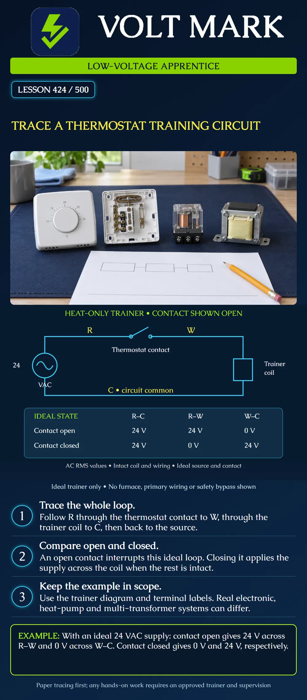
Trace a simple heat-only thermostat training loop from its 24 VAC source through a contact and a relay coil to circuit common. Explain the ideal open-contact and closed-contact voltage relationships without treating the drawing as a universal thermostat installation diagram.
This is an original paper-circuit exercise. Any later physical activity must use an instructor-approved low-voltage trainer with suitable protection and qualified supervision. Do not apply this drawing to a furnace, boiler, heat pump or line-voltage thermostat.
The model assumes an ideal 24 VAC source, intact conductors, an intact compatible relay coil, and an ideal mechanical contact. Values are AC RMS. There are no electronic leakage paths, additional loads, control boards, safety switches or measurement errors in the model. The source circle represents the trainer's low-voltage AC supply; its primary supply and protection are outside the drawing. No coil-operated contacts or actual heating load are shown.
R identifies the supply side feeding the contact in this exercise. W identifies the switched heat-call side leading to the trainer coil. C identifies the other side of the source and the coil's return connection. The thermostat is represented by a contact that can open or close the path from R to W.
The rectangular load symbol is explicitly labeled trainer coil. Its purpose is to show a load between W and C, not to specify the construction or resistance of a particular relay. C is the circuit common in this model; it is not an equipment-ground terminal. Wire colors on the poster are for readability, not conductor identification rules.
Start at the source's R-side connection. Follow the top conductor to R and then to the thermostat contact. Continue from the contact's W side along the conductor to the coil. Pass through the coil to the lower conductor marked C, and return to the other side of the source.
This is a tracing direction for learning. AC current reverses direction; the drawing does not show permanent DC positive and negative terminals.
The poster shows the contact open. In the ideal model, that gap interrupts the only complete load-current path. The coil is not energized. Because no current flows through the intact coil, its ideal voltage drop is zero, so W and C are at the same potential in this model.
The ideal voltage relationships are: R–C: 24 VAC. R–W: 24 VAC. W–C: 0 VAC.
The full source voltage appears across the open contact. Therefore, an open switch is not automatically a point with zero voltage across it. This is a paper prediction, not a reason to touch or test an installed circuit.
Now imagine the contact closed while every other assumption remains unchanged. R connects to W through an ideal zero-resistance contact. The coil has a complete path to the source through C and receives the 24 VAC supply.
The ideal voltage relationships become: R–C: 24 VAC. R–W: 0 VAC. W–C: 24 VAC.
The closed contact's ideal voltage drop is zero. That does not mean the connected conductors are de-energized relative to C; both R and W are now 24 VAC from C in the model. Always name both points when discussing a voltage.
The table is not a universal field troubleshooting chart. Actual equipment can include electronic switching, power-stealing circuits, controller inputs, protective devices and other paths. An instrument can display values affected by those arrangements. Source voltage and contact voltage drop are not necessarily the ideal numbers.
A real thermostat also may delay or cycle an output according to its configuration. A screen that says heat is requested is not, by itself, evidence that an output has changed or that equipment has produced heat. The exercise is only about the stated contact-and-coil model.
Do not calculate coil current by treating an AC coil as a simple resistor unless the exercise explicitly supplies a suitable model. The poster provides no coil impedance or current rating and therefore supports no current calculation.
Resideo's RC840T guide describes compatibility with two-wire mechanical or battery-operated thermostats and three-wire R/C/W thermostats. Its diagrams distinguish those arrangements. The product controls a line-voltage load and calls for electrician installation; this lesson does not reproduce its line-voltage wiring or installation steps.
Resideo's PRO TH4000 installation guide provides different diagrams for different system types and identifies terminal functions for the applicable configuration. The existence of those alternatives matters: one simplified heat-only loop cannot establish the correct wiring for every thermostat.
These documents provide product context only. Our circuit and voltage table are an original idealized training model, not a claim about the internal design of either referenced product.
An instructor gives a learner two copies of the poster circuit. On the first, leave the contact open and mark the gap that prevents a complete path. On the second, draw the contact closed and trace the full loop with a pencil. Do not add a jumper to a real device.
Next, label each proposed voltage observation with both endpoints. Replace the vague note “24 volts at W” with “24 VAC between W and C in the ideal closed-contact state.” A complete description makes the reference point explicit.
Finally, suppose the instructor changes the model by opening the lower return conductor. The learner should state that the intact-wiring assumptions no longer hold. The original closed-contact table cannot simply be reused as a complete prediction for the altered circuit. Identify the change before reasoning further.
Q1. What is the complete path in the ideal closed-contact model?
Q3. With the contact closed, what is the ideal voltage across W–C?
Q4. Does zero volts across a closed contact prove both sides are safe to touch?
Resideo RC840T installation guide, 69-2562EF-05, revision 08-22: https://customer.resideo.com/resources/Techlit/TechLitDocuments/69-0000s/69-2562EF.pdf Resideo PRO TH4000 series installation guide, 69-1928EFS-04: https://customer.resideo.com/resources/techlit/TechLitDocuments/69-0000s/69-1928EFS.pdf
Product-specific wiring is not generalized. The trainer schematic, assumptions, ideal voltage table and questions are original instructional material. No universal terminal colors, current rating or national installation rule is invented.
Mistake: Expecting zero volts across the ideal open thermostat contact. Correction: Name both endpoints and trace the intact coil return: R–W is 24 VAC in the stated open-contact model.
Mistake: Interpreting zero volts across the closed contact as de-energized wiring. Correction: Keep the reference explicit; R and W can both be 24 VAC relative to C while R–W is zero.
Mistake: Using the ideal table after an extra return break is introduced. Correction: Record which assumption changed and analyze the altered circuit instead of reusing the intact-loop results.
Texas journeyman, 15 questions, scored by topic against the 70% mark. No card, and no account needed to start.
Free study material for low-voltage apprentices. This is a national foundation course: requirements differ by state and by local jurisdiction, and a practice that is common in one place is not a rule everywhere. Nothing here is a licence, a certification, or authority to work unsupervised, and completing it does not count as apprenticeship hours or continuing-education credit. Check the codes adopted where you are working, the licensing authority for that work, and your employer's safety programme. VoltMark is not affiliated with, endorsed by, or sponsored by NFPA, OSHA, NICET, BICSI, FOA, or any state or local licensing authority.

Electrician licensing exam prep: practice questions, timed exam simulations, and step-by-step help finding every answer in the NEC.