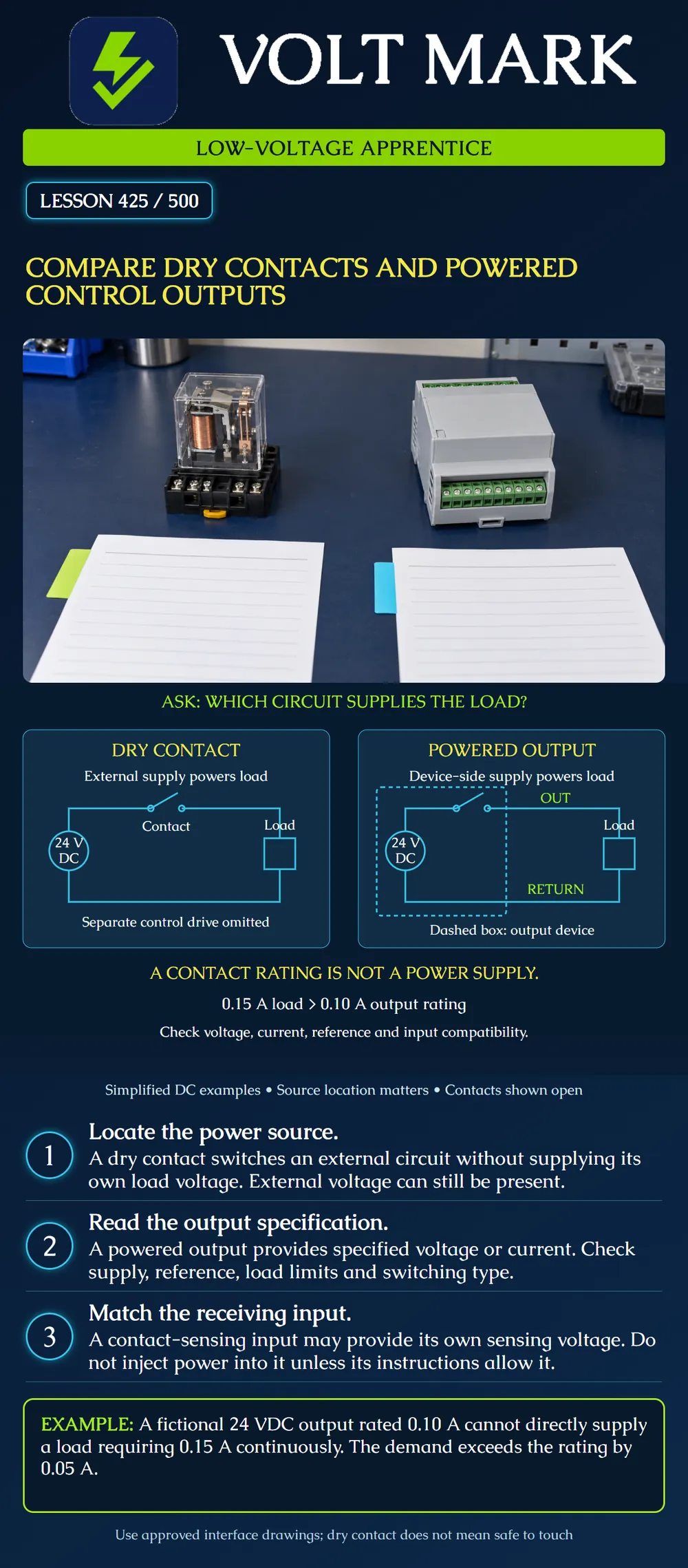
Identify where an output circuit obtains its load power. Distinguish a dry contact from a powered output and explain why output ratings and receiving-input requirements must be checked before connecting equipment.
This lesson uses original simplified DC drawings and a paper-rating exercise. It does not authorize wiring, applying test voltage, forcing controller outputs or bypassing equipment. Follow the exact product instructions, approved interface drawing and qualified supervision for any physical work.
A dry contact provides a switching connection without intentionally supplying its own load voltage to that connection. A separate circuit supplies the energy being switched. The device operating the contact may itself need power; that does not mean its power supply is connected to the switched contact circuit.
Dry does not mean that an installed terminal is voltage-free or safe to touch. Once connected, the contact can have voltage applied from the external circuit. An open contact can have voltage across it, and a closed contact can carry load current within its ratings.
A contact's voltage and current ratings describe what it can switch under stated conditions. They do not describe a voltage or current that the contact generates. Check the applicable AC or DC rating and load category rather than transferring one rating to every kind of load.
A powered output presents specified voltage or current to the load or receiving device, using its associated supply. That supply may be integrated or connected through designated device power terminals. Determine the actual arrangement from the documentation.
Not every electronic output generates power. Some solid-state outputs switch an external supply, and sourcing and sinking arrangements have different connections. Analog outputs also have specified signal ranges and loading limits. Therefore, the broad term electronic output does not establish whether an output is powered, isolated or compatible with a particular input.
The left drawing has an external 24 VDC source, an open dry contact and a load. Follow the complete loop from the external source through the contact and load, then along the lower return to the source. The separate mechanism or control drive that operates the contact is omitted.
The right drawing puts the source and switching function inside a dashed output-device boundary. OUT leads to the external load and RETURN completes its circuit. This is one simplified sourcing-output example, not a universal internal circuit or terminal map.
Both switches are drawn open, so neither ideal load is energized in the illustrated state. The distinction is where the load supply belongs, not whether the output is currently on. Protection, device input power, internal electronics and installation details are omitted. The drawings are conceptual examples, not construction instructions.
A contact-sensing input can provide a sensing signal that passes through the external contact. Such an input is asking for a compatible contact closure, not necessarily an added voltage source. Applying a powered output directly can be wrong even when both products are described as low voltage.
Functional Devices describes a dry-contact-input relay family whose own control circuitry supplies the sensing signal through the external contact. Its guidance distinguishes the contact closure from separately applied device power. That model family is an example; determine the exact input requirements for the equipment in front of you.
Functional Devices also describes a logic-board family with both powered 24 VAC outputs and a dry-contact output. The presence of both types on one device demonstrates why a technician must identify the particular terminal group rather than assume every output is identical. The poster's 24 VDC drawings are original conceptual examples, not that board's wiring.
Schneider Electric's surge-protection FAQ describes dry contacts used for remote status reporting and provides contact ratings for the specified products. It also shows that the contact state during normal powered operation can differ from the contact's de-energized naming convention. Do not infer the system's alarm meaning from NO or NC alone; read the actual state table.
An instructor specifies a fictional powered output: Nominal output: 24 VDC. Maximum continuous load current: 0.10 A. Proposed load's specified continuous current: 0.15 A.
The proposed demand is greater than the output limit: 0.15 A − 0.10 A = 0.05 A. That difference is 50 mA.
The load fails this continuous-current compatibility check. Do not connect it directly based on the voltage match alone. A suitable approved interface or a different output arrangement may be needed, but this lesson does not select one.
Even a proposed load below 0.10 A would require the remaining checks. Startup current, inductive-load behavior, output protection, shared limits, signal compatibility and other manufacturer restrictions are not established by this one number. Do not declare a design approved from a single successful comparison.
“The relay says 24 V, so it supplies 24 V.” Determine whether that number is a coil rating, a contact limit or an actual powered output specification.
“The two products use the same voltage, so they connect directly.” Check what the receiving input expects and what reference or return is required.
“Dry means no voltage can be there.” External circuit voltage may be present.
“COM is ground.” A relay's COM can simply be the common switching contact. It does not automatically identify a power return or equipment ground.
“A status LED proves the load operated.” An indication can report a command or internal state without proving the external action.
For each instructor-provided device excerpt, identify the output type, energy source, maximum permitted load, required reference or return, and receiving-input requirement. Draw a boundary around the source of load power. Mark unknown facts instead of guessing.
State whether the available information establishes compatibility. If the input requires an isolated contact and the proposed output supplies voltage, identify the mismatch and refer it for an approved interface design. Do not experiment by injecting power.
Q1. Does a dry contact itself provide the load supply voltage?
Functional Devices, Versatility of Dry Contact Input RIB Relays: https://blog.functionaldevices.com/industry-insights/versatility-of-dry-contact-input-rib-relays Functional Devices, General Purpose Logic Circuit Device Spotlight: https://blog.functionaldevices.com/product-guidance/general-purpose-logic-circuit-device-spotlight Schneider Electric, dry contacts in specified surge protection devices, FA301214: https://www.se.com/us/en/faqs/FA301214/
Only the relevant interface distinctions were used. Product-specific ratings, overrides and installation instructions are not generalized. Diagrams, fictional ratings and questions are original instructional material.
Texas journeyman, 15 questions, scored by topic against the 70% mark. No card, and no account needed to start.
Free study material for low-voltage apprentices. This is a national foundation course: requirements differ by state and by local jurisdiction, and a practice that is common in one place is not a rule everywhere. Nothing here is a licence, a certification, or authority to work unsupervised, and completing it does not count as apprenticeship hours or continuing-education credit. Check the codes adopted where you are working, the licensing authority for that work, and your employer's safety programme. VoltMark is not affiliated with, endorsed by, or sponsored by NFPA, OSHA, NICET, BICSI, FOA, or any state or local licensing authority.

Electrician licensing exam prep: practice questions, timed exam simulations, and step-by-step help finding every answer in the NEC.