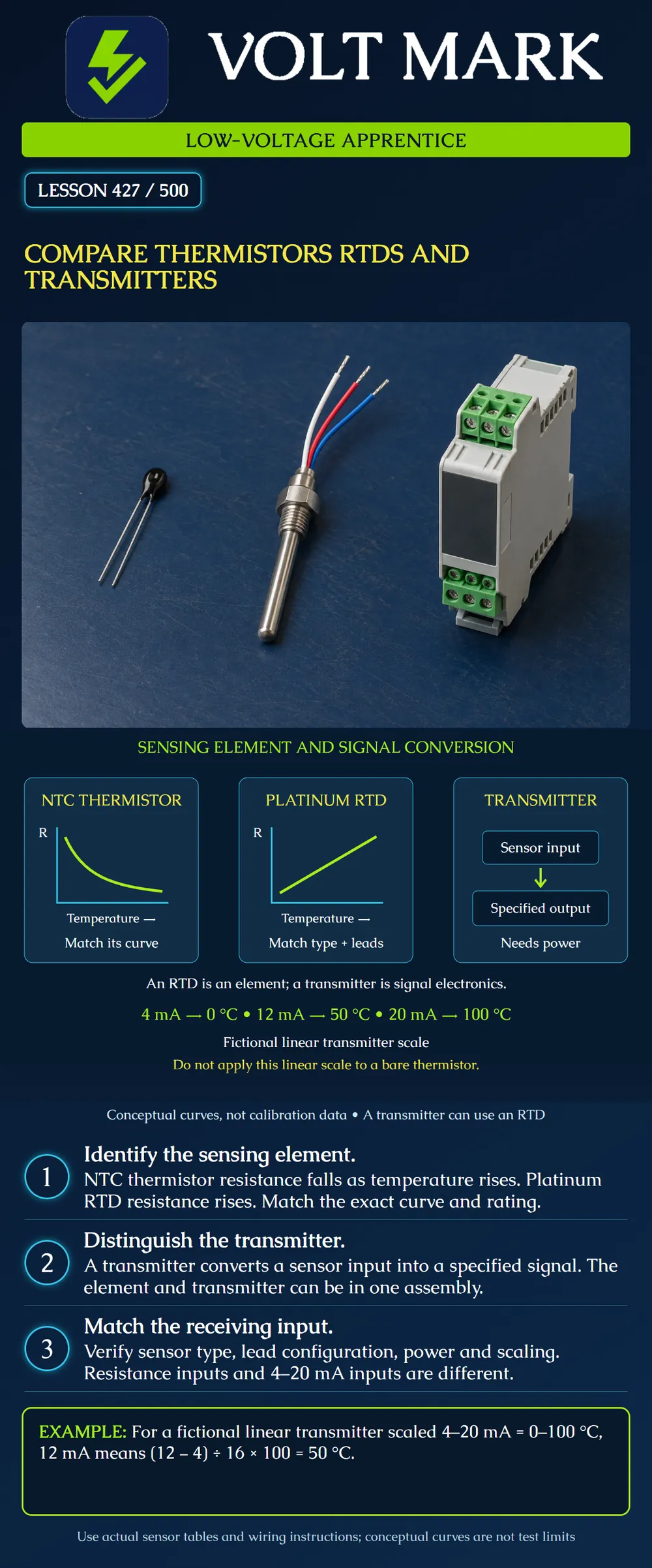
Distinguish two resistance-sensing technologies from the electronics that transmit a measurement. Identify the information needed to match a sensor or transmitter to a controller, and calculate a temperature from a fictional linear current-output scale.
This lesson is a conceptual comparison and paper exercise. The poster curves are illustrative only; they contain no calibration values. Use the actual product data, configuration and approved procedure for field work. This lesson does not authorize changing input modes, injecting signals or measuring resistance on connected equipment.
A thermistor is a temperature-sensitive resistive element. For the NTC type shown, resistance decreases as temperature increases, with a nonlinear relationship. PTC thermistors also exist; the descending curve does not describe them.
A nominal resistance alone is not a complete specification. Match the reference temperature, resistance-temperature curve, tolerance and application limits. Two elements can share a nominal resistance at one temperature while differing elsewhere. The controller or transmitter must use the appropriate curve.
DwyerOmega's thermistor FAQ identifies base resistance, curve and packaging as selection factors. Its comparison article emphasizes matching the electronics to the sensor curve. The poster's curve shows only direction and shape, not a specific manufacturer's table.
RTD means resistance temperature detector. The poster uses a platinum RTD example, whose resistance increases with temperature. Its response is more nearly linear than the NTC example, but the exact characteristic and tolerance still matter.
Record the nominal resistance, reference temperature, coefficient or curve, accuracy class where specified, and lead arrangement. Do not substitute an element just because it is called an RTD.
DwyerOmega explains that a two-wire measurement includes lead resistance, which can affect the result. Three- and four-wire arrangements address lead effects in different ways and require compatible instrumentation. Wire count is part of the interface, not a reason to guess terminal connections from color.
A transmitter accepts a compatible sensor signal and converts it into a specified output. It can be mounted separately or included in the same assembly as the sensing element. An RTD and a transmitter are therefore not mutually exclusive choices: an RTD can feed a transmitter.
Omega's TX94A manual provides a model-specific example of a transmitter accepting a specified platinum RTD and producing a 4–20 mA output. The manual identifies particular input and range options. The lesson does not transfer that model's wiring, isolation or ratings to all transmitters.
A transmitter needs power, including loop power where that is the specified arrangement. A bare resistance element uses excitation supplied by its measuring circuit; it is not itself a 4–20 mA transmitter. A controller resistance input and a current input interpret different electrical quantities.
An instructor defines a fictional transmitter with: 4 mA corresponding to 0 °C. 20 mA corresponding to 100 °C. A linear temperature output between those endpoints.
The signal span is 20 − 4 = 16 mA. At 12 mA, the amount above the lower endpoint is 12 − 4 = 8 mA. The fraction of span is 8 / 16 = 0.5. Temperature is 0 + 0.5 × 100 = 50 °C.
Do not calculate 12 / 20 × 100. That would ignore the 4 mA lower endpoint and produce an incorrect 60 °C result.
A second instructor-defined transmitter uses the same 4–20 mA signal but is scaled from −20 to 80 °C. At 12 mA it is still halfway through its span, so its indicated temperature is −20 + 0.5 × 100 = 30 °C. The current value has meaning only with the configured engineering scale.
These examples assume the signal is valid and within the normal measurement span. A reading outside the span may have a model-specific error meaning; do not invent a universal fault interpretation.
The instructor supplies three fictional labels: A: NTC element with a specified resistance-temperature table. B: Platinum RTD with a specified nominal resistance and three-wire arrangement. C: Powered transmitter with a specified current output and configured temperature range.
For A, identify the table and the controller's supported resistance-sensor setting. For B, identify the RTD characteristic and compatible lead arrangement. For C, identify the required supply, current-input compatibility, load limits and engineering scale.
The label “temperature sensor” is insufficient for all three. A receiving input configured for A does not automatically interpret B correctly, and C cannot be treated as a bare resistance element.
A plausible temperature on a display does not prove that the correct curve is selected. Two incompatible curves can produce similar values near one point. A successful single-point comparison cannot establish performance across the whole application range.
Likewise, an exact midpoint calculation does not prove physical accuracy. It only demonstrates the configured scale. Sensor accuracy, transmitter error, wiring effects and installation conditions remain separate considerations.
Do not measure resistance on an energized circuit. Any actual verification requires the approved isolation and measurement procedure and qualified supervision. This lesson provides no live test sequence or replacement authorization.
Using an instructor-provided document, identify whether its external terminals present raw resistance or a transmitter output. Write down the exact sensor characteristic or output scale. Then list missing compatibility information instead of selecting a replacement by appearance.
Q1. What happens to an NTC thermistor's resistance as temperature rises?
DwyerOmega, FAQ about Thermistors: https://www.dwyeromega.com/en-us/resources/thermistor-faq DwyerOmega, NTC Thermistors vs. RTDs: https://www.dwyeromega.com/en-us/resources/rtd-vs-thermistors DwyerOmega, RTD wire configurations: https://www.dwyeromega.com/en-us/resources/rtd-2-3-4-wire-connections Omega TX94A manual M4124: https://assets.omega.com/manuals/M4124.pdf
The BAPI overview fetch returned 403 and was not treated as reviewed content. Graphs, current-scale examples and matching exercises are original instructional material. No universal sensor accuracy, wiring color or calibration interval is asserted.
Mistake: Selecting a thermistor only by its nominal resistance. Correction: Match reference temperature, complete resistance-temperature curve, tolerance and controller setting.
Mistake: Treating an RTD transmitter output as bare sensor resistance. Correction: Identify the external interface and use the documented current, voltage or resistance input type.
Mistake: Dividing 12 mA by 20 mA to find the span fraction. Correction: Subtract the 4 mA lower endpoint and divide by the 16 mA span, then apply the configured engineering endpoints.
Texas journeyman, 15 questions, scored by topic against the 70% mark. No card, and no account needed to start.
Free study material for low-voltage apprentices. This is a national foundation course: requirements differ by state and by local jurisdiction, and a practice that is common in one place is not a rule everywhere. Nothing here is a licence, a certification, or authority to work unsupervised, and completing it does not count as apprenticeship hours or continuing-education credit. Check the codes adopted where you are working, the licensing authority for that work, and your employer's safety programme. VoltMark is not affiliated with, endorsed by, or sponsored by NFPA, OSHA, NICET, BICSI, FOA, or any state or local licensing authority.

Electrician licensing exam prep: practice questions, timed exam simulations, and step-by-step help finding every answer in the NEC.