Interpret a voltage command using its configured endpoints. Calculate a percentage from an explicitly linear 0–10 VDC scale, contrast it with 2–10 VDC, and distinguish a command from evidence of physical operation.
This lesson is a paper exercise using an original ideal scale. It does not authorize connecting a meter, injecting voltage, forcing outputs or changing actuator settings. The actual device documentation, approved sequence and qualified supervision govern physical work.
A control voltage represents information according to its configured scale. The same voltage can represent a position request, a temperature target or another quantity. A note saying “signal is 6 volts” is incomplete unless the signal type, reference and scale are identified.
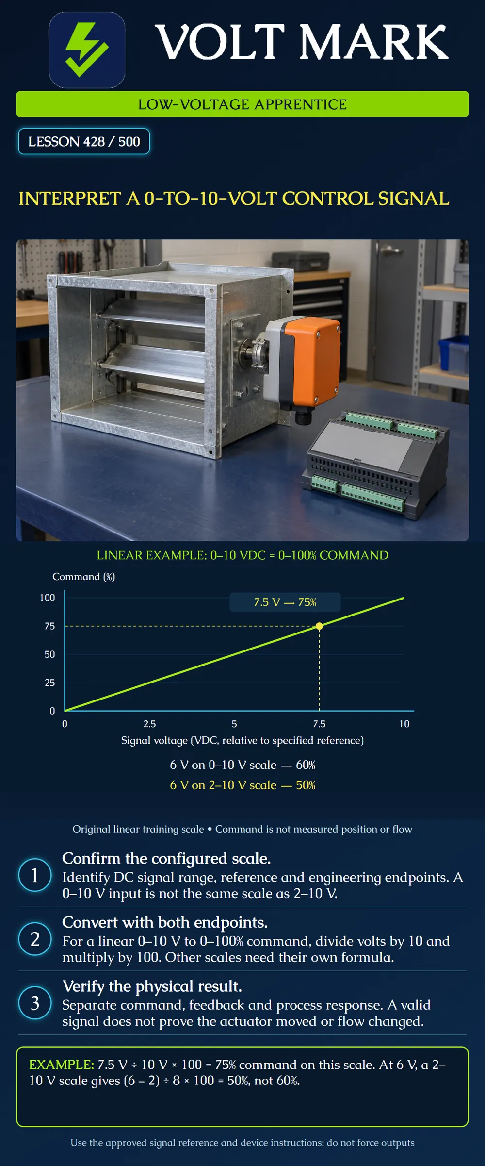
For this lesson the signal is DC, the range is 0 to 10 V, and the mapped command is 0 to 100 percent with a direct linear relationship. These assumptions are printed above the graph. They do not describe every input with a similar terminal label.
The horizontal axis is signal voltage relative to the specified signal reference. The vertical axis is command percentage. The line starts at 0 V and 0 percent and ends at 10 V and 100 percent. The marked point at 7.5 V lies at 75 percent.
The dashed guides help the learner read the two coordinates. They are graph aids, not conductors. The graph is an original mathematical training illustration, not a measured actuator-performance curve.
For this scale: Command percentage = signal voltage / 10 V × 100.
Examples: 0 V corresponds to 0%. 2.5 V corresponds to 25%. 5 V corresponds to 50%. 7.5 V corresponds to 75%. 10 V corresponds to 100%.
For 7.5 V, 7.5 / 10 = 0.75, and 0.75 × 100 = 75%. This describes the command represented by the signal. It does not say that the damper is physically at 75% travel or that airflow is 75% of maximum.
An instructor supplies a second fictional device with a direct linear 2–10 VDC input mapped to 0–100% command. Its voltage span is 10 − 2 = 8 V. At 6 V, the signal is 6 − 2 = 4 V above its lower endpoint: (6 − 2) / (10 − 2) × 100 = 50%.
On the original 0–10 V scale, 6 / 10 × 100 = 60%. Both calculations are correct for their respective scales. The mistake would be applying the first scale to the second device.
The general linear conversion is: Engineering value = lower engineering endpoint + [(signal − lower signal endpoint) / (upper signal endpoint − lower signal endpoint)] × (upper engineering endpoint − lower engineering endpoint).
Use consistent units and the actual configured endpoints. Do not extrapolate below or above the documented range and claim the equipment must behave that way.
Suppose a fictional controller maps 0–10 V to a temperature target of 10–30 °C. The engineering span is 20 °C. At 7.5 V: 10 + (7.5 / 10) × 20 = 25 °C.
The signal still represents 75% of the configured span, but the engineering value is 25 °C, not 75 °C. Record both the units and endpoints to avoid this error.
Some configurations reverse the direction of the relationship or limit the usable travel. An actual control point must be interpreted using its configured direction and sequence. The poster assumes direct action and does not specify any default direction for real equipment.
A control input is not automatically the device's operating-power connection. Belimo's actuator guide discusses separate power and control-signal functions as well as position-feedback outputs. Check the actual model instead of assuming the signal supplies motor power.
The signal reference is also defined by the device. Do not substitute equipment ground for a specified signal common or add a common-to-ground bond based on this lesson. Compatibility includes the permitted output loading, receiving-input requirements and documented reference arrangement.
This lesson deliberately provides no terminal numbers, universal wire colors or test connections.
Belimo's guide distinguishes an actuator's control input from its position-feedback output and explains that damper position and airflow have a nonlinear relationship influenced by the installation. That supports three separate questions: What command was sent? What position was reported or verified? What physical process result occurred?
For an original paper scenario, a controller record reports 7.5 V command while a separate record reports 50% position. First verify timestamps, point definitions and the expected response conditions supplied by the instructor. Do not conclude solely from those two numbers that the actuator is defective. A command describes an intended action; it does not identify the cause of a mismatch.
A zero-volt observation alone also does not establish whether the controller intentionally requested the lower endpoint, the supply is unavailable, wiring has a problem or another condition exists. The exact device defines signal-loss and fault behavior. There is no universal fail position established by the title “0–10 V.”
Belimo's control-signal article identifies both 0–10 VDC and 2–10 VDC among proportional-control signals and discusses configurable control characteristics. Its application guide separates actuator inputs, power and feedback. These sources support the distinctions; the lesson's graphs and calculations are original examples.
The older article's additional signal-conversion suggestions are not used as installation instructions here. Any actual conversion or interface must satisfy the connected devices' requirements.
Using an instructor-provided point record, write the signal range, engineering range, units, direction, reference and data timestamp. Calculate a value only after those facts are known. Then list the separate evidence needed to establish the physical response.
Q1. On the fictional 0–10 V to 0–100% scale, what is 7.5 V?
Belimo, Understand Control Signal Jargon: https://www.belimo.com/br/en_US/blog/Understand-Control-Signal-Jargon Belimo, Damper Actuator Applications Guide, electronic actuators and flow characteristics: https://www.belimo.com/mam/americas/technical_documents/Support%20material/belimo_damper-applications_guide_en-us.pdf
The graph, fictional endpoints, arithmetic and scenarios are original teaching material. No universal output tolerance, fault threshold, terminal assignment or signal-loss position is invented.
Mistake: Reading 6 V as 60% on a configured 2–10 V input. Correction: Subtract 2 V and divide by the 8 V span; this configuration represents 50%.
Mistake: Calling 7.5 V proof of 75% damper travel or airflow. Correction: Describe the 75% command and obtain separate position and process observations.
Mistake: Diagnosing a broken wire from zero volts alone. Correction: Check the device's command, supply, reference and documented signal-loss behavior through the approved procedure.
Texas journeyman, 15 questions, scored by topic against the 70% mark. No card, and no account needed to start.
Free study material for low-voltage apprentices. This is a national foundation course: requirements differ by state and by local jurisdiction, and a practice that is common in one place is not a rule everywhere. Nothing here is a licence, a certification, or authority to work unsupervised, and completing it does not count as apprenticeship hours or continuing-education credit. Check the codes adopted where you are working, the licensing authority for that work, and your employer's safety programme. VoltMark is not affiliated with, endorsed by, or sponsored by NFPA, OSHA, NICET, BICSI, FOA, or any state or local licensing authority.

Electrician licensing exam prep: practice questions, timed exam simulations, and step-by-step help finding every answer in the NEC.