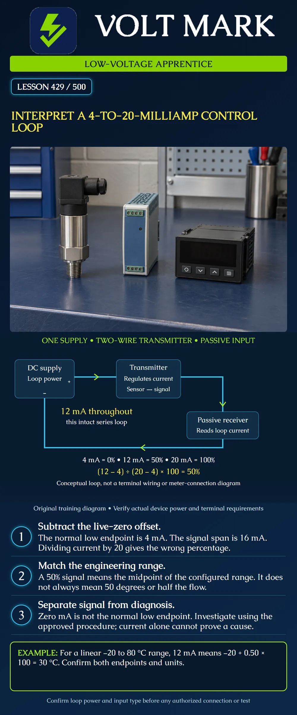
Read a conceptual current loop, distinguish live zero from zero current, and convert a valid linear 4–20 mA signal into its configured engineering value. Explain what that result does and does not establish.
This is a classroom interpretation lesson, not permission to open an operating circuit, inject a signal, reconfigure an input, or bypass a control. The drawing represents one external DC supply, one two-wire loop-powered transmitter and one passive receiving input. Other arrangements require their own manufacturer diagrams. The illustration deliberately omits field terminal numbers and protective details.
On the poster, trace supply positive to the transmitter, onward to the receiving input, and back to supply negative. There is one series path. A transmitter varies the loop current to represent a measured quantity; the receiving device interprets that current. In an intact series loop, the current is the same through the components, although their voltage drops differ.
The drawing's arrows indicate conventional current around the external circuit. The line enters and leaves the component boxes rather than representing a bypass around them. A sensor is conceptually associated with the transmitter; this does not specify a particular sensor connection. The receiver is passive with respect to loop excitation: it does not add a second loop power supply in this example. Actual equipment may use different supply arrangements.
The normal linear signal range starts at 4 mA and ends at 20 mA. Its span is 20 − 4 = 16 mA. Four milliamps represents the configured low engineering endpoint, commonly called live zero. It does not necessarily represent zero degrees, zero pressure, or zero equipment output.
Original classroom formula: Fraction of configured span = (measured mA − 4) / 16 Engineering value = low endpoint + fraction × (high endpoint − low endpoint)
For 12 mA: (12 − 4) / 16 = 8 / 16 = 0.50 = 50%. The tempting answer 12 / 20 = 60% forgets the 4 mA offset.
For this lesson's fictional temperature range, the low endpoint is −20 °C and the high endpoint is 80 °C. The temperature span is 100 °C. At 12 mA, the indicated value is −20 + 0.50 × 100 = 30 °C. It is not 50 °C.
Original scale table for that same fictional configuration: 4 mA → 0% → −20 °C 8 mA → 25% → 5 °C 12 mA → 50% → 30 °C 16 mA → 75% → 55 °C 20 mA → 100% → 80 °C
These are exact arithmetic examples. They do not specify instrument accuracy, calibration tolerance or display resolution.
Before interpreting a saved reading, identify the point tag, engineering units, transmitter range and receiving input range. Record whether the conversion is linear. A 4–20 mA label by itself does not prove the complete process conversion is linear; a configured conversion such as square-root extraction changes the interpretation.
Consider two fictional linear pressure points. Point A maps 4–20 mA to 0–100 psi. Point B maps it to 0–300 psi. Both report 12 mA. Point A represents 50 psi; Point B represents 150 psi. The identical electrical signal carries a different numerical meaning because the engineering endpoints differ. Neither answer proves an actuator moved or the actual pressure sensor is accurate.
A loop needs sufficient voltage to support the transmitter, receiving load and wiring drops while meeting equipment limits. A long run or added load can affect that voltage budget. Do not infer unlimited distance from the use of a current signal. Read the device-specific supply and allowable-load requirements.
An input that supplies loop excitation is not interchangeable with the passive input drawn here. Do not connect an additional supply merely because a transmitter has two wires. Identify the complete interface from its documentation. No universal supply voltage, spare percentage or terminal assignment is prescribed by this poster.
A zero-current indication is outside the normal 4–20 mA measurement span. It is not the same as the normal low endpoint. It can justify investigation, but that one observation does not identify a broken conductor, failed supply, failed transmitter or reading problem by itself. Check the actual instrument's diagnostic behavior and the site's approved procedure.
Likewise, do not assign a universal fault meaning to every value just below 4 or above 20 mA. Some devices allow overrange, underrange or defined diagnostic outputs. Device configuration and documentation determine how the receiving system treats them. This lesson does not prescribe common alarm thresholds as nationwide requirements.
Use a fictional linear level transmitter configured for 2 to 10 feet. Its span is 8 feet.
Using a trainer drawing and saved configuration records, mark the loop supply, transmitter and receiving input. Label each interface as documented rather than guessing from wire colors. Write down both engineering endpoints and the conversion type. Convert a provided current value without touching equipment. Have the instructor compare the interpretation with the trainer documentation.
Precision Digital, Back to Basics: Part 1 — The Fundamentals of 4–20 mA Current Loops: https://www.predig.com/indicatorpage/back-basics-fundamentals-4-20-ma-current-loops Supports basic loop roles, series current and live-zero scaling. Its general design recommendations are not adopted here as universal requirements.
NI, 4–20 mA Current Loop Fundamentals, System Design, and Setup: https://www.ni.com/en/shop/data-acquisition/fundamentals--system-design--and-setup-for-the-4-to-20-ma-curren.html Supports loop supply/load considerations. Use actual equipment documentation for a design.
The drawing, numerical examples, exercises and checks are original classroom material. No manufacturer-specific installation is reproduced.
Mistake: Treating 4 mA as zero degrees regardless of configuration. Correction: Use the configured lower engineering endpoint; it is −20 °C in this lesson's temperature example.
Mistake: Calculating percent of span by dividing measured current by 20. Correction: Subtract 4 mA and divide by 16 mA before applying the engineering range.
Mistake: Adding a second supply because a two-wire transmitter needs power. Correction: Identify whether the receiving input already provides loop excitation and use the complete approved interface drawing.
Local licensing, installation and approval requirements must be checked for the actual project.
Texas journeyman, 15 questions, scored by topic against the 70% mark. No card, and no account needed to start.
Free study material for low-voltage apprentices. This is a national foundation course: requirements differ by state and by local jurisdiction, and a practice that is common in one place is not a rule everywhere. Nothing here is a licence, a certification, or authority to work unsupervised, and completing it does not count as apprenticeship hours or continuing-education credit. Check the codes adopted where you are working, the licensing authority for that work, and your employer's safety programme. VoltMark is not affiliated with, endorsed by, or sponsored by NFPA, OSHA, NICET, BICSI, FOA, or any state or local licensing authority.

Electrician licensing exam prep: practice questions, timed exam simulations, and step-by-step help finding every answer in the NEC.