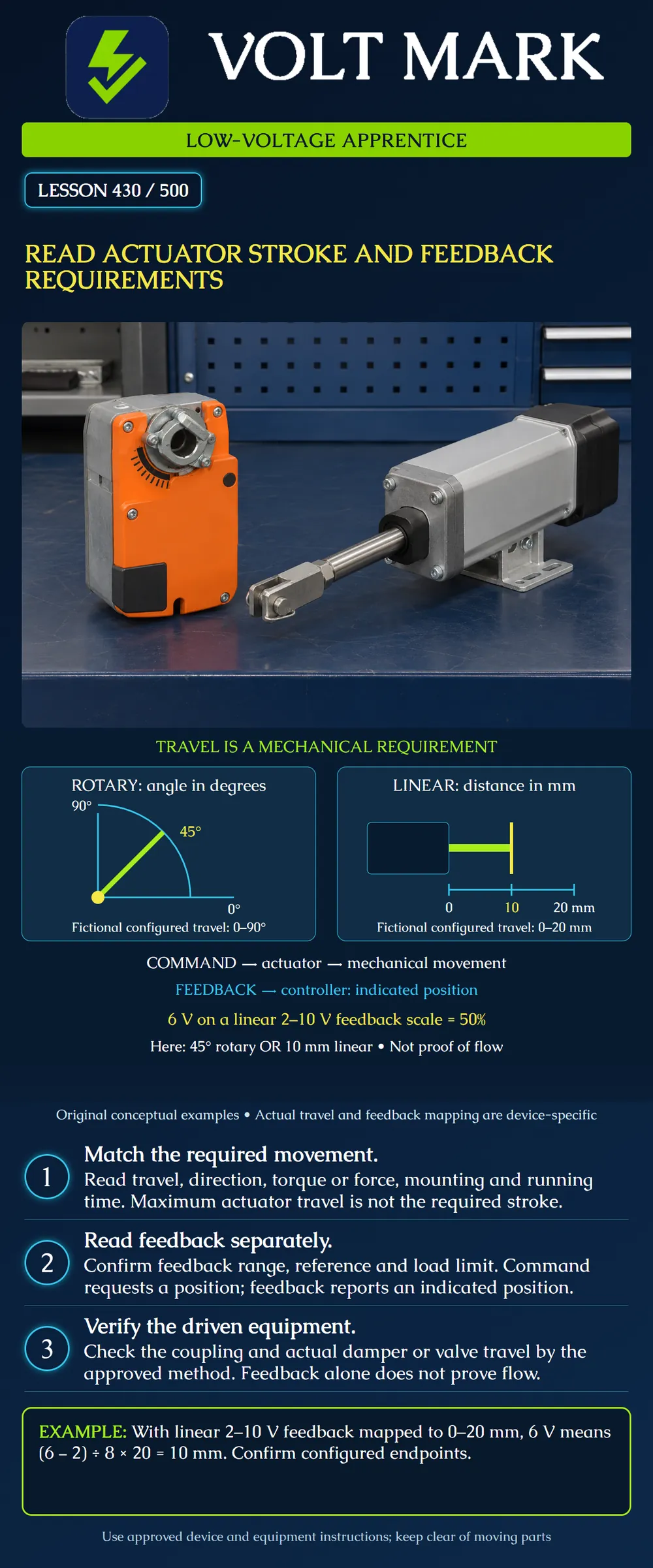
Read an actuator requirement without confusing available travel, requested position, reported position and the physical response of the driven equipment.
This lesson concerns low-voltage building-control interfaces and document interpretation. The two poster mechanisms and their numerical ranges are fictional teaching examples. They are not installation drawings, product selections or permission to move operating equipment. No mechanical stop, direction switch, wiring, override or adaptation setting is to be changed from this lesson.
A rotary actuator turns a shaft; travel is described as an angle. A linear actuator moves along a straight path; stroke is described as a distance. Keep the units attached. A requirement for 20 mm is not satisfied merely because a rotary device can turn 90 degrees. A linkage can translate motion, but its approved geometry and compatible assembly must be established.
The left illustration represents an assigned 0–90-degree travel with a marker at 45 degrees. The right represents an assigned 0–20-mm travel with a marker at 10 mm. Both markers are halfway through their assigned ranges. They do not describe the same physical motion, force or application.
Read the driven equipment requirement before using the actuator's maximum capability. A fictional actuator capable of 100 degrees does not authorize forcing a damper that requires only 90 degrees. Likewise, a longer available stroke does not automatically make a replacement compatible with a shorter-stroke valve. Identify the approved combination and any required manufacturer setup.
For the actual job, record the equipment tag, actuator model and revision, required movement, units, direction, mounting arrangement, available torque or force, running time, supply, command interface, feedback interface and required behavior on loss of power or command.
Keep torque and linear force in different fields. They are not interchangeable quantities. Include operating conditions that the approved selection depends on. A matching signal range does not by itself establish mechanical suitability.
Original desk comparison: Requirement A: rotary movement, 0–90 degrees, compatible shaft coupling. Candidate B: linear movement, 0–20 mm, stem connection. Conclusion: Both can have a 2–10 V control interface, yet they do not satisfy the same movement requirement. The matching voltage label is insufficient.
Command is the requested position sent toward the actuator. Feedback is a separate reported quantity returned toward the controller. Read what the feedback actually represents and its reference, range, permissible load and endpoint mapping.
Do not assume a controller point labeled position is an independently measured damper blade or valve plug position. It may represent the actuator's own position indication. A slipping coupling could leave the actuator and driven equipment disagreeing. Review the actual assembly and verification method.
The poster uses a fictional linear 2–10 V feedback mapping. Six volts is halfway between 2 and 10: (6 − 2)/(10 − 2) = 4/8 = 0.50. For the fictional 0–90-degree mapping, 0 + 0.50 × 90 = 45 degrees. For the fictional 0–20-mm mapping, 0 + 0.50 × 20 = 10 mm.
Neither result establishes air or liquid flow. The equipment's position-to-flow relationship and actual system conditions are separate from the position calculation.
A position percentage needs a defined origin and direction. In an original reversed classroom mapping, 2 V represents 20 mm and 10 V represents 0 mm. At 4 V, the fraction is (4 − 2)/8 = 0.25. The indicated position is 20 + 0.25 × (0 − 20) = 15 mm. In the increasing mapping, the same 4 V would mean 5 mm.
Therefore, record both endpoints explicitly. Do not replace those endpoints with assumptions such as more voltage always means more opening. An action described as extending or retracting also needs its mechanical meaning for the particular valve or damper.
Belimo's LMB24-SR-T sheet dated2025-12-23 describes a24V rotary damper actuator with2–10V command and feedback, a feedback load limit, selectable direction, maximum95-degree rotation, adjustable stop and95seconds per90degrees. Its application section directs sizing to the damper manufacturer's specifications. These are model-specific data, not defaults for every actuator. An incongruous position-indication row mentions millimeter stroke; do not interpret that isolated row as converting this rotary product into a linear actuator. Resolve conflicting selection information with the manufacturer.
Belimo's SH24A-MOD200 sheet dated2026-01-30 describes a24V linear actuator with maximum200mm stroke, adjustable travel, configurable feedback and adaptation options. It illustrates why available travel, configured limits and feedback settings must be distinguished. The poster's20mm example is not a configuration instruction for that product. Its regional data sheet does not establish acceptance on any particular US project.
For a supervised desk exercise, use previously recorded command, feedback and observation data. Identify timestamps and whether enough permitted travel time elapsed. A snapshot taken during movement can differ from a settled result. Apply the actual acceptance tolerance and timing criteria; this lesson sets neither.
Original example: Requested position:75%. Reported position:50%. Difference:25percentage points. That arithmetic documents a difference, not its cause. Missing time information, wrong scaling, a mechanical restriction, a coupling issue or another condition may require investigation. Do not jump from the subtraction to an unverified diagnosis.
If command and feedback agree at75%, describe that agreement precisely. Do not write airflow verified unless the approved process measurement establishes it. Also distinguish a position indication from a discrete end switch. A switch reports its configured state; it does not provide a continuous travel measurement by itself.
Belimo LMB24-SR-T technical data sheet,2025-12-23: https://www.belimo.com/mam/general-documents/datasheets/en-us/belimo_LMB24-SR-T_datasheet_en-us.pdf Belimo SH24A-MOD200 technical data sheet,2026-01-30: https://www.belimo.com/mam/general-documents/datasheets/en-gb/belimo_SH24A-MOD200_datasheet_en-gb.pdf
Source-specific summaries support document-reading concepts; numerical poster examples, comparison records and exercises are original. No terminal wiring is reproduced.
Mistake: Selecting an actuator by signal range while ignoring rotary versus linear motion. Correction: Compare the required movement, units, coupling and force or torque with the approved assembly.
Mistake: Assuming higher voltage always means more opening. Correction: Record both feedback endpoints and direction; the reversed example yields 15 mm at 4 V.
Mistake: Treating actuator position feedback as proof of driven-equipment flow. Correction: Identify what the feedback senses and retain the separate mechanical and process verification.
Texas journeyman, 15 questions, scored by topic against the 70% mark. No card, and no account needed to start.
Free study material for low-voltage apprentices. This is a national foundation course: requirements differ by state and by local jurisdiction, and a practice that is common in one place is not a rule everywhere. Nothing here is a licence, a certification, or authority to work unsupervised, and completing it does not count as apprenticeship hours or continuing-education credit. Check the codes adopted where you are working, the licensing authority for that work, and your employer's safety programme. VoltMark is not affiliated with, endorsed by, or sponsored by NFPA, OSHA, NICET, BICSI, FOA, or any state or local licensing authority.

Electrician licensing exam prep: practice questions, timed exam simulations, and step-by-step help finding every answer in the NEC.