Trace the coil and contact paths of a simple permissive interlock, predict four input combinations, and distinguish expected logic from verified physical operation.
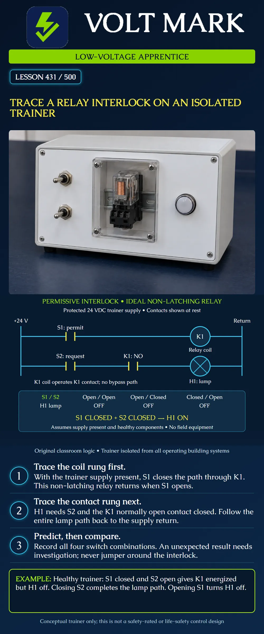
The original illustration is a conceptual two-rung trainer circuit. A protected 24 VDC training supply feeds the left positive rail and right return rail. The trainer is separate from all operating building systems. Its exact component selection, protection, coil suppression, sockets and terminal wiring belong to the approved trainer documentation, not this conceptual drawing.
An instructor-approved trainer may be energized for controlled demonstration under its own procedure; isolated from building equipment does not mean its terminals are always de-energized. This lesson authorizes no work on field interlocks or emergency systems. The output is a trainer indicator lamp, not a motor, lock, fan or alarm function.
S1 is the permit switch. S2 is the request switch. Each is shown open in the resting drawing. K1 identifies a non-latching relay: its coil is on the upper rung, and its normally open contact is on the lower rung. The shared K1 identifier links the contact function to that coil. It is not an extra wire between the rungs.
H1 is the lamp on the lower rung. Its circle and cross identify an indicator symbol. The vertical rails connect both rungs to the same example supply. The right rail is the supply return, not an instruction to use equipment grounding conductors as circuit return.
Normally open describes the relay contact's unoperated condition. For this selected non-latching example, the contact closes when the coil operates and returns open when the coil releases. The resting contact symbol is not a promise that the circuit is safe to touch. Actual latching relays have different behavior and are outside the exercise.
Start at the positive rail. Follow the conductor to S1. When S1 is open, the path stops there and K1 is not energized in this ideal example. When S1 closes, the path continues through the K1 coil to the return rail. The coil can operate.
Trace through the load, not around it. A line crossing the coil would create a different circuit. The poster has no path that bypasses S1 or shorts across K1. Assume the supply and components are healthy for the prediction table. Do not use the ideal model to declare real hardware fault-free.
Start again at the positive rail. Follow the path through S2, then the K1 normally open contact, then H1 and finally the return rail. S2 alone cannot light H1 if the K1 contact is open. An energized K1 alone cannot light H1 if S2 is open.
The permit condition and request condition must both be present. This is a simple permissive interlock: the request is allowed to reach the lamp only when the relay contact permits a complete circuit. There is no holding or seal-in branch. There is no latch, delay, reset function or monitored safety contact in this example.
Assumptions: supply present, correctly assembled trainer, healthy non-latching relay, healthy switches and indicator, settled states rather than switching transients.
S1 open; S2 open: K1 released; K1 contact open; H1 off. S1 open; S2 closed: K1 released; K1 contact open; H1 off. S1 closed; S2 open: K1 operated; K1 contact closed; H1 off. S1 closed; S2 closed: K1 operated; K1 contact closed; H1 on.
There are two binary inputs, so 2 × 2 = 4 combinations. Three predict an off lamp; one predicts an on lamp. That count describes the logic table. It is not a failure rate or a reliability claim.
Original sequence exercise: Begin with both switches open. Close S2: the lamp remains off because permission is absent. Close S1: the coil operates and the lamp turns on. Open S1 while leaving S2 closed: the coil releases and the lamp turns off. Close S1 again with S2 still closed: the lamp turns on again.
This last behavior matters: the example can re-enable its output when permission returns. It does not contain a separate manual restart requirement. Do not promote it to a field safety design.
Complete the prediction table before any instructor demonstration. During an approved demonstration, record the input states, expected coil state, expected lamp state, observed indication and any mismatch. A relay click is not independent proof that its contact carried current. A dark lamp is not proof that every conductor is de-energized.
If H1 unexpectedly remains lit after S1 opens, the observation contradicts this ideal circuit's prediction. A wrong connection, an unintended parallel path, a contact problem or another condition may need investigation. Do not diagnose one cause from the lamp alone, and do not bypass the contact to obtain a desired indication.
If K1 appears to operate but H1 stays off with S2 closed, the coil and load paths must still be considered separately. The observation does not establish whether the lamp, supply, contact, connection or interpretation is responsible. Record the facts and refer the trainer to the instructor's approved troubleshooting process.
Before a hands-on session, the instructor must establish the actual equipment instructions, permitted actions, power control and wiring-change process. Any changes occur under that process with the required energy isolation and verification. This poster does not provide a meter-connection procedure, contact rating selection or protection design.
General-purpose relays must be used within their coil and contact specifications. Manufacturer guidance warns that incorrect coil voltage and loads exceeding contact ratings can damage a relay, including contact welding. Therefore the statement coil off means contact open is an expected healthy condition, not a guarantee under every failure.
A single ordinary relay and lamp demonstration does not establish a safety performance level, fire-alarm acceptance, access-control egress compliance or equipment protective function. Those applications require their own approved designs and verification.
OMRON, Overview of General Purpose Relays: https://www.ia.omron.com/support/guide/36/introduction.html Supports coil/contact operation and distinction between ordinary and latching operation. OMRON, Safety Precautions for General Purpose Relays: https://www.ia.omron.com/product/cautions/36/safety_precautions.html Supports specification-dependent application, correct coil voltage and contact-rating limits.
The diagram, permissive sequence, truth table and exercises are original teaching material, not a manufacturer wiring diagram.
Mistake: Tracing the lamp through the upper rung because coil and contact share K1. Correction: Use K1 as the functional link, then trace the separate lower-rung path through S2, the contact and H1.
Mistake: Calling the circuit a manual-reset interlock. Correction: Read the no-latch sequence: with S2 closed, restoring S1 re-enables H1 in this example.
Mistake: Treating a relay click as proof that the lamp circuit carried current. Correction: Record coil operation and the required load observation separately; unexpected results need instructor investigation.
Answer: K1 is released, so its normally open contact interrupts the lamp's lower-rung path.
Answer: No. The lower rung still has an open request switch, so the lamp lacks a complete circuit.
Answer: There is no separate restart latch; S1 operates K1 and completes the already-requested lower-rung path.
Answer: No. A wiring error or other unintended path can also contradict the healthy model; record the observation and use the instructor's approved investigation.
Texas journeyman, 15 questions, scored by topic against the 70% mark. No card, and no account needed to start.
Free study material for low-voltage apprentices. This is a national foundation course: requirements differ by state and by local jurisdiction, and a practice that is common in one place is not a rule everywhere. Nothing here is a licence, a certification, or authority to work unsupervised, and completing it does not count as apprenticeship hours or continuing-education credit. Check the codes adopted where you are working, the licensing authority for that work, and your employer's safety programme. VoltMark is not affiliated with, endorsed by, or sponsored by NFPA, OSHA, NICET, BICSI, FOA, or any state or local licensing authority.

Electrician licensing exam prep: practice questions, timed exam simulations, and step-by-step help finding every answer in the NEC.