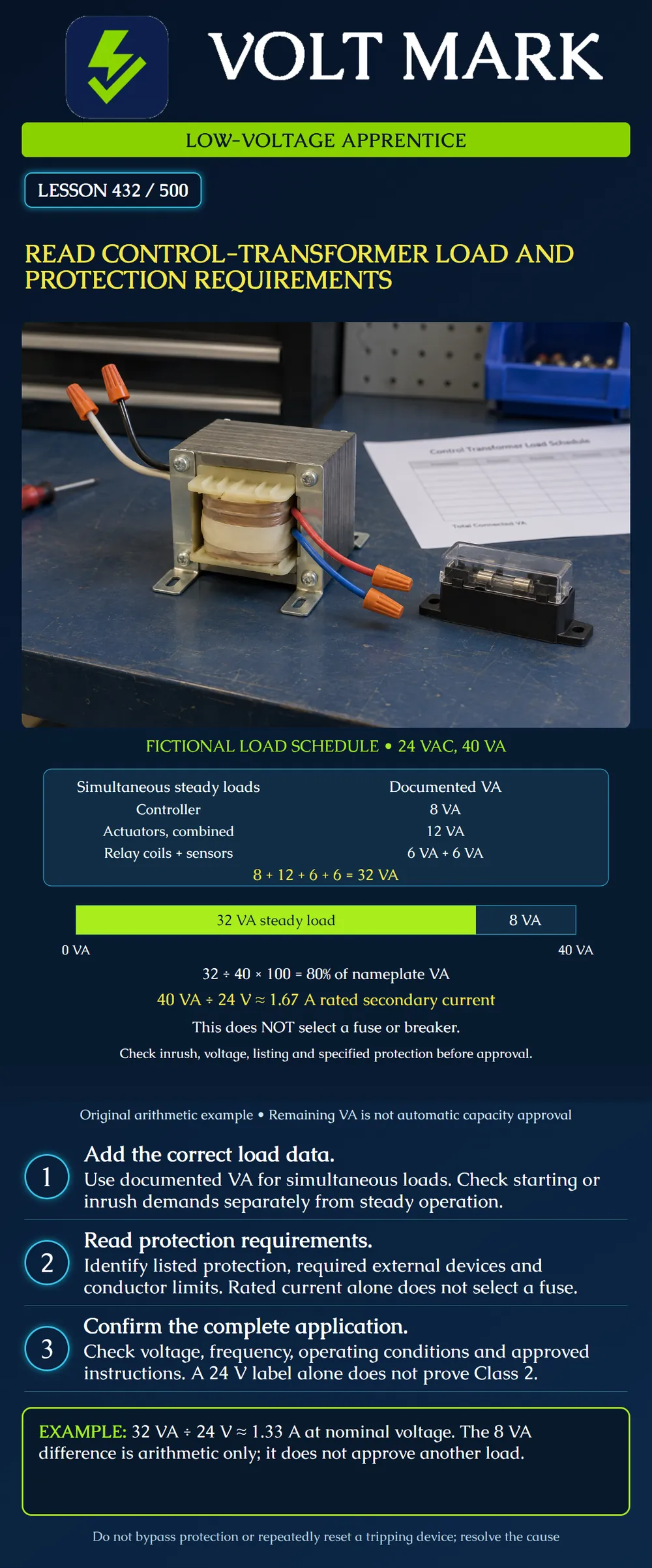
Read a control-transformer load schedule, calculate nominal secondary current, and identify the information needed to verify loading and protection without guessing a fuse size.
The poster addresses document review for low-voltage AC controls. Its 24 VAC, 40 VA transformer and all loads are fictional. This lesson does not instruct work on a line-voltage primary, replacement of protection, or connection of additional equipment. Actual transformer selection and installation must follow approved design, product instructions and applicable requirements.
First: what is the transformer rated to supply? Second: what does the connected equipment require during relevant operating states? Third: how are the transformer, conductors and equipment protected?
These questions use related information but are not interchangeable. A VA rating describes apparent-power capacity under specified conditions. A load schedule describes demand. A protection requirement determines the approved protective arrangement. Dividing VA by voltage answers a current calculation; it does not answer all three questions.
For every connected item, record its tag, quantity, supply voltage, documented VA or relevant input-current data, operating state and source document. Distinguish the total for a group from the value for one device so quantities are not counted twice.
The original classroom schedule is: Controller: 8 VA. Actuators, combined: 12 VA. Relay coils, combined: 6 VA. Sensors, combined: 6 VA. All listed groups operate simultaneously in the example. Arithmetic total: 8 + 12 + 6 + 6 = 32 VA.
The actuators are already combined at 12 VA; do not multiply that entry by the number of actuators again. The total relay-coil entry is likewise already combined.
This is a simplified sum of documented steady-load VA. It is not an exact phasor analysis or evidence of the installation's measured power factor. For actual equipment, follow its specified supply-sizing method. Do not substitute watts for VA without adequate supporting data. DC device watts also do not directly establish the AC input demand of an intervening power supply.
For this single-phase nominal-voltage example: Rated secondary current = 40 VA / 24 V = 1.6667 A, approximately 1.67 A. Scheduled steady-load current = 32 VA / 24 V = 1.3333 A, approximately 1.33 A. Scheduled VA as a fraction of rating = 32 / 40 = 0.80, or 80%. Arithmetic difference = 40 − 32 = 8 VA.
The bar represents exactly those values. Eighty percent is the outcome of these chosen numbers. This lesson does not impose a universal 80-percent transformer-loading rule. The remaining eight VA is not automatically available for expansion: startup, voltage regulation, environment, manufacturer limits and project requirements remain to be evaluated.
Some coils and other equipment can demand more current during starting or pickup than during settled operation. Record the documented inrush and operating values and the states in which loads can start together. A transformer that passes a steady-load sum can still fail the actual application requirements.
Schneider Electric's FAQ for its 9070 Type T and TF products distinguishes continuous rating from momentary high-inrush demands and directs selection using inrush and sealed VA with the product's regulation guidance. That is a model-family selection method, not permission to assume every 40 VA transformer can support any brief overload.
Original document-review exercise: The 32 VA schedule is complete for steady operation, but actuator startup data are missing. Write the result as steady arithmetic checked; startup suitability unresolved. Do not write transformer approved. The missing item is evidence, not a reason to invent a startup multiplier.
Also distinguish control-load pickup from transformer energization inrush. They are different events that can matter to the selected protective arrangement.
Identify what the product actually provides: for example, an inherently limited construction, a specified built-in breaker, or requirements for external protection. Then identify what that protection covers and any remaining installation requirements.
Functional Devices' retired TR40VA001US data sheet identifies a Class 2 product with inherently limited overcurrent protection. Its TR75VA001 data sheet identifies a Class 2 product with a circuit breaker. These different descriptions illustrate why a technician must read the exact model instead of assuming that all low-voltage transformers have the same protection. The retired product is a historical document-reading example, not a purchase recommendation.
Neither the 24 V output marking nor a calculation alone establishes Class 2 status. Use the actual listing, markings and approved installation conditions. Do not assume that a secondary protective feature resolves every primary or conductor-protection requirement.
The value 1.67 A calculated on the poster is rated secondary current. It is not a directive to install a 1.67 A fuse, round up to a nearby breaker, or remove an existing protective device. Device type, location, rating, operating characteristic and coordination must come from the applicable requirements and approved selection.
Record transformer tag and model, document revision, secondary voltage and VA, operating conditions, load schedule, simultaneous states, startup information, protective arrangement and unresolved items. Separate verified facts from assumptions.
For the fictional example, an honest note is: Nominal steady schedule32VA against40VA; arithmetic difference8VA. Nominal calculated load current1.33A. Startup suitability and protection selection require review of the actual equipment documentation.
Do not repeatedly reset a tripping protective device to obtain continued operation. Report the symptom and follow the approved investigation procedure. A trip is not permission to increase the protective rating or bypass the device.
Schneider Electric FAQ FA99381, 9070 Type T/TF control-transformer overload and inrush guidance; modified2025-12-15: https://www.se.com/us/en/faqs/FA99381/ Functional Devices TR40VA001US data sheet,20240502, marked retired: https://hosted.functionaldevices.com/downloads/datasheets/TR40VA001US.pdf Functional Devices TR75VA001 data sheet,2025-08-21: https://hosted.functionaldevices.com/downloads/datasheets/TR75VA001.pdf
The two Functional Devices sheets show60Hz in the drawing and50/60Hz in the specification table. This lesson does not resolve that discrepancy for installation; verify actual nameplate and manufacturer instructions. No wiring colors, protection rating or primary connection instruction is taken from these examples.
Mistake: Multiplying an already-combined actuator VA row by device count again. Correction: Label per-device and combined entries, then extend quantities only once.
Mistake: Treating the example's 80% loading as a universal permitted limit. Correction: Report the assigned 32/40 ratio and apply the actual product's startup and installation requirements.
Mistake: Increasing protection to stop nuisance tripping. Correction: Preserve the specified protection and refer loading, inrush and fault evidence for qualified investigation.
Texas journeyman, 15 questions, scored by topic against the 70% mark. No card, and no account needed to start.
Free study material for low-voltage apprentices. This is a national foundation course: requirements differ by state and by local jurisdiction, and a practice that is common in one place is not a rule everywhere. Nothing here is a licence, a certification, or authority to work unsupervised, and completing it does not count as apprenticeship hours or continuing-education credit. Check the codes adopted where you are working, the licensing authority for that work, and your employer's safety programme. VoltMark is not affiliated with, endorsed by, or sponsored by NFPA, OSHA, NICET, BICSI, FOA, or any state or local licensing authority.

Electrician licensing exam prep: practice questions, timed exam simulations, and step-by-step help finding every answer in the NEC.