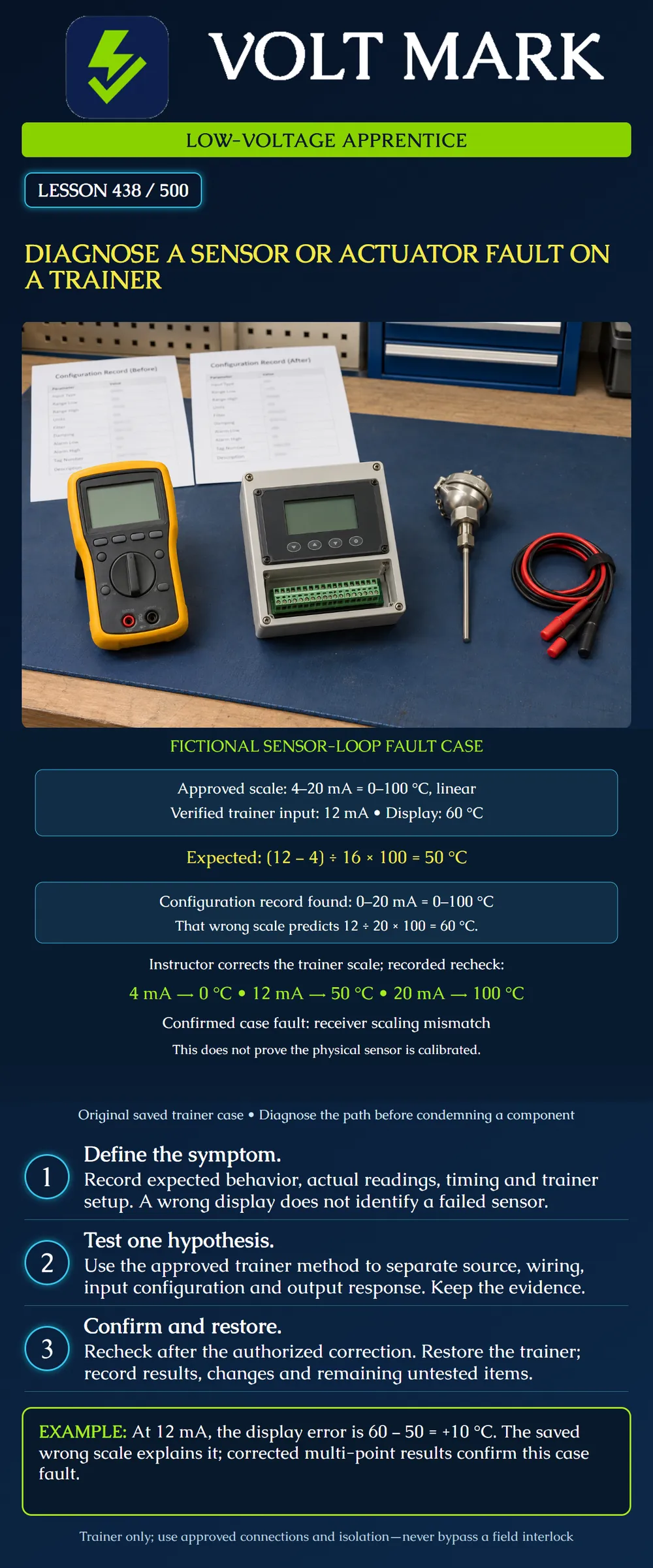
Diagnose a trainer fault using evidence from a known configuration and controlled checks. Distinguish a proven case fault from an untested assumption about a sensor or actuator.
This is an original fictional trainer case with supplied readings and configuration records. It is isolated from operating building systems. No real sensor is disconnected, no signal is injected and no output is moved during preparation of this lesson. For a physical demonstration, the instructor must use the trainer's approved procedures, correct instruments and energy-control method.
The poster deliberately solves a sensor-loop configuration fault rather than assuming the sensor element has failed. Learning to avoid an unnecessary replacement is part of diagnosis.
The approved fictional trainer documentation specifies a linear4–20mA input representing0–100°C. A known midpoint input of12mA should therefore give: (12−4)/(20−4)×100=50°C.
The saved observation is a displayed60°C. The indicated error relative to the expected result is: 60−50=+10°C.
These values are original exercise data. They do not establish an acceptable tolerance for a real instrument.
A display error could arise in the source signal, connection, input circuit, configuration, units, displayed point mapping or another part of the path. Record hypotheses separately from facts.
At this stage, sensor defective is unsupported. The case supplies a verified12mA input at the trainer receiver boundary under its approved setup. That evidence narrows the investigation toward interpretation of the received signal, but it does not prove every part of the complete sensor assembly is healthy.
A point labeled temperature can still be mapped to the wrong source. Confirm the identity of the displayed point as part of the record.
The saved receiver configuration is0–20mA mapped linearly to0–100°C, which contradicts the approved4–20mA mapping.
That incorrect configuration predicts: 12/20×100=60°C.
This explains the observed midpoint value. The agreement between hypothesis and observation supports the scaling hypothesis, but the exercise also includes a controlled correction and recheck before calling it the confirmed case fault.
Do not repair a scaling error by deliberately miscalibrating the sensor or adding an arbitrary display offset. Correct the identified configuration under the authorized trainer procedure.
In the fictional case, the instructor corrects the receiver to the approved scale, preserving the original configuration and recording the change. Supplied post-correction data are: Known4mA input; display0°C. Known12mA input; display50°C. Known20mA input; display100°C.
The low, middle and high checks now agree with the original mapping. The supported conclusion is that a receiver scaling mismatch caused the demonstrated indication error, and the receiver interpretation passed these three exercise checks after correction.
The test does not establish calibration of the physical temperature sensor if it was replaced by the trainer's known signal. It also does not establish full-system performance in service. State those limits rather than treating a passed subsystem check as proof of everything.
Fluke's loop-troubleshooting guidance describes transmitter simulation as a way to examine a receiving loop separately from the original transmitter. Its calibration guidance distinguishes measuring, simulating and sourcing current. These functions are not interchangeable: the power source and circuit arrangement must match the instrument and device instructions.
This lesson does not reproduce a connection procedure. In a hands-on session, identify exactly which components remain in the test path and which are substituted. A receiver test with a substitute signal cannot automatically certify the removed sensor.
For a genuine sensor-element test, the reference stimulus and sensor type must be appropriate. For a resistance-based sensor, its curve and lead configuration matter. A convenient resistor is not automatically a valid substitute for an arbitrary temperature sensor.
For an actuator trainer, document the approved supply, command range, direction, travel limits, feedback mapping and expected timing before diagnosing failure. The Belimo LMB24-SR-T sheet illustrates that these are distinct model-specific characteristics; its ratings are not defaults for every trainer.
Original unresolved actuator example: Requested position50%. Saved feedback10%. Observed shaft still moving when the snapshot was taken. The evidence is insufficient to declare a fault before the permitted travel time and settled condition are evaluated.
Original configuration hypothesis: The command uses2–10V while the assumed interpretation uses0–10V. Verify the actual configuration and mapping before replacing the actuator. At6V, the first scale represents50%, while the second represents60%. That arithmetic identifies a possible interpretation discrepancy; it is not evidence that a particular physical actuator has failed.
A mechanism that remains stationary after a valid settled command still requires appropriate checks of its power, interfaces, state and mechanical assembly. Do not force the shaft, bypass an interlock or energize an unknown terminal to see what happens.
After an authorized physical trainer exercise, remove temporary substitutions through the approved procedure, restore the intended configuration and wiring, and recheck the required normal behavior. Retain the before/after record and identify any tests not completed.
A useful case report includes: Trainer ID and drawing revision. Reported symptom. Expected behavior and its source. Actual readings and timestamps. Instrument and test-boundary information. Hypothesis and evidence. Authorized correction. Recheck results. Restoration status and remaining limitations.
Do not close the exercise with fixed if only the symptom disappeared without a supported explanation or required restoration checks.
Fluke, Troubleshooting a4–20mA loop using mA simulate: https://www.fluke.com/en-us/learn/blog/calibration/troubleshooting-a-4-20-ma-loop-using-ma-simulate Fluke, Eliminating sensor errors in temperature control loop calibrations: https://www.fluke.com/en-ca/learn/blog/calibration/eliminating-sensor-error-in-temperature-controll-loop-calibrations Belimo LMB24-SR-T technical data sheet: https://www.belimo.com/mam/general-documents/datasheets/en-us/belimo_LMB24-SR-T_datasheet_en-us.pdf
Sources support test-boundary and interface concepts. The fault, readings, configuration evidence, correction and exercises are fictional original teaching material, not records of physical testing performed by the author.
Mistake: Replacing the sensor before checking the receiver's saved scale. Correction: Compare the verified input and approved map with the receiver configuration; the case shows a 0–20 versus 4–20 mA mismatch.
Mistake: Using only the 20 mA high point to approve the conversion. Correction: Check low and middle points too, because both conflicting scales show 100 °C at 20 mA.
Mistake: Reporting the three-point receiver test as physical sensor calibration. Correction: State the substituted-signal boundary and leave the original sensor's accuracy outside that result.
Texas journeyman, 15 questions, scored by topic against the 70% mark. No card, and no account needed to start.
Free study material for low-voltage apprentices. This is a national foundation course: requirements differ by state and by local jurisdiction, and a practice that is common in one place is not a rule everywhere. Nothing here is a licence, a certification, or authority to work unsupervised, and completing it does not count as apprenticeship hours or continuing-education credit. Check the codes adopted where you are working, the licensing authority for that work, and your employer's safety programme. VoltMark is not affiliated with, endorsed by, or sponsored by NFPA, OSHA, NICET, BICSI, FOA, or any state or local licensing authority.

Electrician licensing exam prep: practice questions, timed exam simulations, and step-by-step help finding every answer in the NEC.