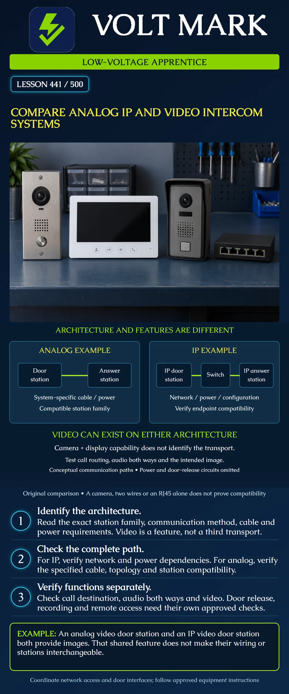
Compare intercom connection architectures and recognize video as a capability that may appear on more than one architecture. Identify the records needed before connecting, replacing or testing stations.
The diagram contains conceptual communication paths. Power, protective details, release relays and locks are not shown. It does not authorize installation, network changes or operation of a controlled door. Product-specific examples establish the distinction between features and transport; they are not purchase recommendations.
How do the stations communicate? What functions does the system provide?
Analog and IP describe different communication arrangements. Video describes the ability to convey an image. Treating analog, IP and video as three mutually exclusive choices would be misleading.
Aiphone's JO-DV page identifies an analog video door station and describes its model-specific cable and monitor-supplied power. Aiphone's IX/IXG page describes IP video intercom products. These examples demonstrate that a camera does not establish which transport or compatible station family is used.
The left diagram shows a door station connected to a compatible answering station through the specified system cabling. Actual analog products can have different station counts, distribution arrangements and power methods. The picture is not a universal point-to-point wiring specification.
Record station models, approved compatible combinations, conductor requirements, permitted route and distance, power arrangement and any required interface units. The number of available conductors alone does not establish suitability. Cable electrical characteristics, condition and length can matter.
Do not connect an analog station to an Ethernet switch because its cable happens to be a category cable or because an adapter makes the connector fit. Some products use familiar cables for proprietary interfaces.
The right diagram shows an IP door station and an IP answering station communicating through a switch. Actual systems may include additional servers, gateways, software clients or cloud services according to the chosen design. The diagram does not imply they are always required or always absent.
Record the approved network ports, addressing method, required communication services, endpoint compatibility and power dependencies. If PoE is used, verify the actual device and switch requirements, including supported power type and budget. The term IP alone does not guarantee PoE support.
Separate a local IP network from Internet connectivity. Whether Internet access is needed for a particular calling, management or mobile feature depends on that product and configuration. An IP label does not, by itself, mean that every local call depends on a cloud service.
A video-capable system needs the intended image at the intended answering endpoint. Verify camera view, lighting conditions, orientation and usable image quality against the project requirements. A visible picture does not prove that the correct door is identified or that two-way audio works.
Original classroom comparison: SystemA uses compatible analog video stations and dedicated manufacturer-specified cabling. SystemB uses compatible IP video stations through an approved network. Both have a camera and answering display. The shared image feature does not make their station interfaces interchangeable.
A hybrid arrangement or a manufacturer-supported retrofit adapter can change the path. It must be documented for the particular devices. Do not infer conversion capability from a passive connector adapter or from the phrase two-wire.
In a saved test record, distinguish these observations: The correct destination receives the call. The answering operator hears the visitor. The visitor hears the operator. The intended camera image appears. The call terminates and returns to the expected idle condition.
These are separate outcomes. Ringing only proves a limited part of the path. Clear audio in one direction does not establish the other direction.
If the project requires multiple destinations, groups, busy behavior or unanswered-call handling, use the actual approved requirements. Do not invent a universal timeout or escalation sequence from this lesson.
An intercom may provide an interface to a door-release function, but that feature does not establish lock-power compatibility, egress compliance or the complete access-control sequence. Identify the responsible team and approved interface requirements.
Similarly, video communication does not automatically mean that recording is enabled or supported. Recording, retention, mobile answering and remote management need their own documented scope and authorized settings. Do not promise a feature based only on an IP or video label.
This lesson provides no release wiring or remote-access configuration instructions.
For each proposed or existing system, make a record with: Exact station models and supported family. Transport and topology. Cabling and approved distance limits. Power source and dependencies. Answering endpoints and call-routing requirements. Audio and video capabilities. Door-control interface, if applicable. Recording or remote features, if applicable. Configuration revision and verification evidence.
Original desk exercise: A record says video intercom;2wires;works. That record is insufficient to determine whether it is analog, a digital non-IP bus, or an IP retrofit arrangement. Retrieve the exact model and documentation before concluding anything about its architecture.
Digital non-IP systems also exist; the poster is a comparison of two examples, not an exhaustive classification of every intercom product.
Original observation: The intended answering station rings and shows the correct image, but the visitor cannot hear the operator.
Record the failed audio direction and the successful functions. Do not call the whole system offline or assume the camera is defective. Review the approved diagnostic process for endpoint settings, audio path and device condition without changing unrelated door or network functions.
Aiphone JO-DV product page: https://www.aiphone.com/products/jo-dv/ Aiphone IX/IXG Series IP Video Intercom: https://www.aiphone.com/products/ix-ixg-series/ Aiphone IP Intercom vs.Analog Intercom: https://www.aiphone.com/blogs/ip-intercom-vs-analog-intercom/
These manufacturer sources support the architecture and feature distinction. Model-specific cable, capacity, power and service details are not generalized. The diagrams, records and exercises are original.
Mistake: Classifying every camera-equipped door station as IP. Correction: Record transport and video capability in separate fields; identify the exact station family before selecting a replacement.
Mistake: Reusing category cable as proof that the station can connect to Ethernet. Correction: Match the cable and interface to the manufacturer's supported arrangement, including power and distance; connector fit is insufficient.
Mistake: Accepting the system because reception sees the visitor. Correction: Record correct call destination, visitor-to-operator audio, operator-to-visitor audio and video as separate outcomes before judging the required functions.
Texas journeyman, 15 questions, scored by topic against the 70% mark. No card, and no account needed to start.
Free study material for low-voltage apprentices. This is a national foundation course: requirements differ by state and by local jurisdiction, and a practice that is common in one place is not a rule everywhere. Nothing here is a licence, a certification, or authority to work unsupervised, and completing it does not count as apprenticeship hours or continuing-education credit. Check the codes adopted where you are working, the licensing authority for that work, and your employer's safety programme. VoltMark is not affiliated with, endorsed by, or sponsored by NFPA, OSHA, NICET, BICSI, FOA, or any state or local licensing authority.

Electrician licensing exam prep: practice questions, timed exam simulations, and step-by-step help finding every answer in the NEC.