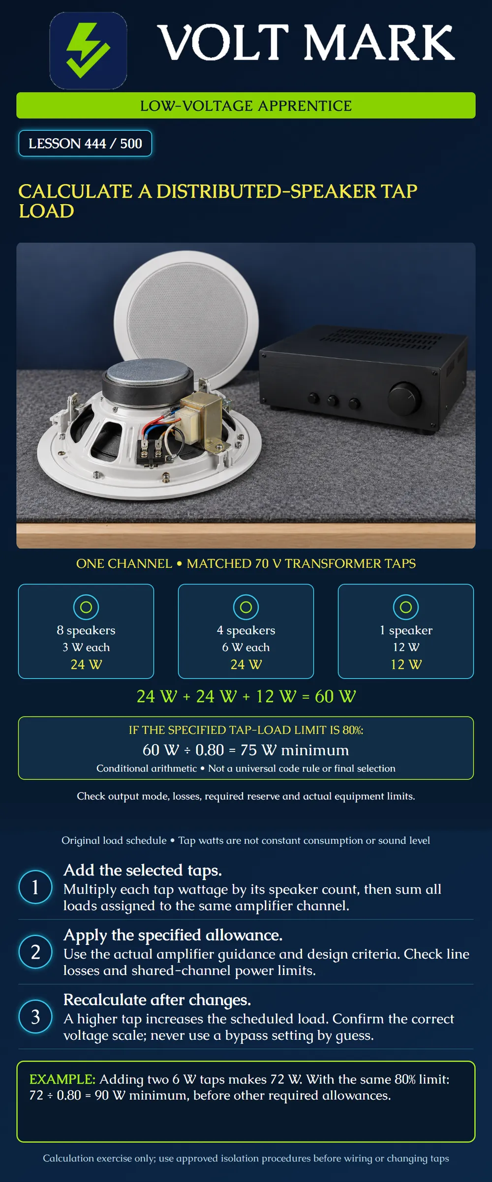
Calculate the total nominal transformer-tap load on a distributed-audio amplifier channel and apply a clearly stated loading allowance without confusing it with a universal rule.
This paper exercise uses compatible transformer-coupled speakers on a fictional 70 V output. It is not a final system design or authorization to touch energized audio terminals. The designated line voltage, amplifier mode, equipment ratings, actual cable losses and project requirements must be verified. “Low voltage” does not establish that a speaker circuit is safe to touch.
A selectable transformer tap specifies a nominal electrical load for a stated line voltage and matching speaker arrangement. Do not substitute the speaker's maximum power-handling label for the selected tap. A cabinet rated to handle more power may be operating on a smaller transformer tap. A label may show different wattages for 70 V and 100 V operation; read the scale matching the actual approved output mode.
An 8-ohm or other low-impedance bypass position is not an additional transformer wattage setting. The calculation in this lesson does not apply to directly paralleling low-impedance drivers. Confirm the product instructions, approved circuit and intended setting before any authorized adjustment.
Tap wattage is not a promise that the speaker constantly consumes that power. Audio amplitude changes with the signal and level. Nor does a tap alone predict loudness, coverage or intelligibility. Those depend on additional speaker and acoustic conditions.
List each speaker identifier, selected tap, voltage scale, channel assignment and quantity. Grouping is useful only when every member actually has the same applicable setting. Keep a traceable list behind each grouped total.
The original poster schedule contains: Group A: eight speakers at 3 W each = 24 W. Group B: four speakers at 6 W each = 24 W. Group C: one speaker at 12 W = 12 W. There are thirteen speakers. The channel tap total is 24 + 24 + 12 = 60 W.
These tap values are fictional available settings for the exercise. They are not asserted to exist on every speaker. A physical cable loop through successive speakers does not make the transformer loads a series circuit; use the approved topology and manufacturer terminals. The poster is a load schedule, not a wiring diagram.
Suppose the selected design guidance limits nominal tap load to 80% of available channel output. For this exercise: Tap total <= 0.80 x amplifier channel rating. Required rating >= 60 / 0.80 = 75 W.
The 80% value is a conditional design assumption used here, not a nationwide electrical-code requirement. Pure Resonance Audio publishes an 80% recommendation for its 70 V sizing guidance. Follow the actual equipment and project requirements; other allowances and operating conditions may govern. The arithmetic threshold of 75 W does not establish that any nominally 75 W product is suitable.
Do not confuse leaving 20% of amplifier rating unused with adding 20% to the load. Adding 20% to 60 W gives 72 W. Then 60/72 is approximately 83.33%, which exceeds this example's 80% loading limit. Dividing by 0.80 gives 75 W; 15 W remains between the tap sum and that rating, equal to 20% of 75 W and 25% of 60 W. The denominator matters.
Check the channel's rating in the intended distributed-voltage mode, along with shared power budgets on multichannel equipment. A total chassis rating does not automatically belong to each output. Do not combine amplifier outputs unless the specific product instructions support that arrangement.
The simple tap sum is not a complete accounting of cable loss, transformer behavior, frequency limitations, required filters, attenuator limits, simultaneous operating demands or expansion reserve. Document how the approved design handles those items. Do not silently double-count an allowance already included in a design method, and do not assume that one generic percentage covers every issue.
An attenuator or intermediate device can introduce its own load and rating constraints. Turning the operator's level control down is not a substitute for designing the permitted load and verifying the equipment limitations. The schedule must reflect the intended permitted configuration.
Add two speakers at 6 W: the total becomes 60 + 12 = 72 W across fifteen speakers. Under the same conditional 80% limit, 72/0.80 = 90 W before other required allowances.
Instead, start with the original schedule and change two existing 3 W taps to 6 W. The increase is two times (6 - 3) = 6 W, not 12 W, because their original 6 W combined load was already counted. The revised total is 66 W; 66/0.80 = 82.5 W.
If the project provides a suitable 100 W channel and the 80% tap criterion applies, its tap ceiling is 80 W. The original 60 W schedule leaves 20 W below that conditional ceiling, not 40 W of unrestricted expansion. Remaining design constraints still apply.
Prepare a schedule with speaker IDs A01-A08 at 3 W, B01-B04 at 6 W and C01 at 12 W. Reconcile the grouped quantities to thirteen individual records. Mark an uncertain voltage scale “verify,” not an assumed wattage. Apply the original 60 W calculation, then the two change scenarios above. For a second hypothetical channel containing five 6 W taps, calculate 30 W and keep that channel's limit separate from the first. Write “arithmetic checked; equipment/design suitability pending” when the actual amplifier, cable and project constraints have not been supplied.
Pure Resonance Audio, How To Choose The Right Commercial Amplifier and 70V Speaker Tap Settings For Your Audio System: https://www.pureresonanceaudio.com/blogs/articles/how-to-choose-amplifier-70v-speaker-taps-for-audio-system Opened directly. Used for selected-tap summation and its explicitly attributed 80% recommendation; the lesson's numbers and scenarios are original.
Shure SR105 Power Amplifier manual: https://pubs.shure.com/view/guide/SR105/en-US.pdf Official indexed excerpt supports the individual-load summation principle. Direct PDF retrieval was unavailable. This legacy product is not recommended or used for present-day ratings.
AtlasIED 70-Volt Rules: https://ftp.atlasied.com/70voltrules Opened during research. Only the transformer/load context was considered. Its broad “safe” voltage statement and ambiguous impedance wording were not adopted as safety or calculation guidance. Sources checked 2026-10-01. No blanket code edition, jurisdictional classification or universal reserve percentage is asserted.
Mistake: Summing cabinet maximum ratings instead of selected transformer taps. Correction: Record each speaker's actual tap on the correct voltage scale and sum those settings for its assigned channel.
Mistake: Adding 20% to 60 W when the stated limit is 80% of amplifier rating. Correction: Divide 60 W by 0.80 to obtain 75 W; check the loading fraction against the stated denominator before selecting equipment.
Mistake: Counting a changed 3 W tap as a new 6 W load. Correction: Add only the 3 W increase for that existing speaker; two such changes raise the original total from 60 W to 66 W.
Texas journeyman, 15 questions, scored by topic against the 70% mark. No card, and no account needed to start.
Free study material for low-voltage apprentices. This is a national foundation course: requirements differ by state and by local jurisdiction, and a practice that is common in one place is not a rule everywhere. Nothing here is a licence, a certification, or authority to work unsupervised, and completing it does not count as apprenticeship hours or continuing-education credit. Check the codes adopted where you are working, the licensing authority for that work, and your employer's safety programme. VoltMark is not affiliated with, endorsed by, or sponsored by NFPA, OSHA, NICET, BICSI, FOA, or any state or local licensing authority.

Electrician licensing exam prep: practice questions, timed exam simulations, and step-by-step help finding every answer in the NEC.