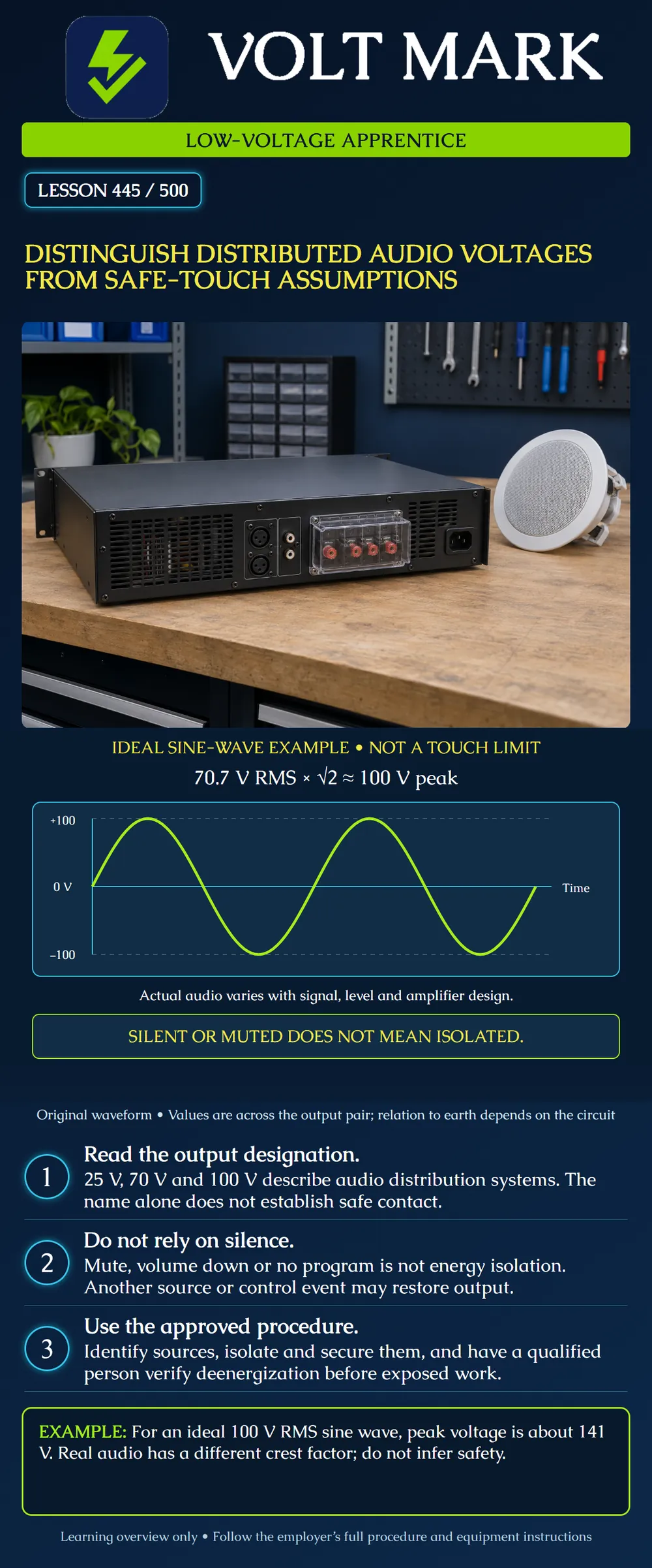
Explain why a distributed-audio label, an idle system or a quiet speaker is insufficient evidence that conductors are safe to touch. Distinguish RMS, instantaneous peak and voltage reference points.
This is a classroom explanation of audio-system hazards, not an energized testing procedure. The waveform is a mathematical example. It does not direct an apprentice to expose, measure or touch speaker terminals. Work must stay within training, authorization and the applicable employer procedure. Requirements depend on the work activity and jurisdiction; this lesson is not a universal permit, licensing or circuit-classification determination.
Distributed systems may be described as 25 V, 70 V or 100 V. These describe an audio distribution arrangement and associated equipment ratings. They do not promise a harmless voltage or identical available energy in every product. The audio output can vary with signal and operating state.
Biamp's Community R.5/R.25 installation manual specifically warns of amplifier voltage/current hazards, particularly in 70 V and 100 V systems. This manufacturer warning contradicts any blanket assumption that all speaker cable is harmless because it belongs to a low-voltage trade. “Low voltage” is used differently in different contexts; do not use the phrase in place of the actual circuit documentation.
Read the amplifier output mode, speaker/transformer ratings, terminal markings and safety instructions. An audio power output is different from a microphone or line-level signal connection even when both carry sound. Familiar connectors or small conductors do not establish the source rating or installation classification.
RMS means root mean square. For an ideal sine wave, the peak magnitude is the RMS value multiplied by the square root of two. 70.7 x 1.41421356 = approximately 99.985 V, rounded to 100 V peak. An ideal waveform with a positive peak of 100 V and a negative peak of -100 V has a peak-to-peak span of 200 V. For an ideal 100 V RMS sine wave, the peak magnitude is approximately 141.4 V and peak-to-peak span approximately 282.8 V.
The poster plots two ideal cycles across an output pair. The vertical values are instantaneous voltage. Time increases to the right; no frequency or period is assigned. The horizontal zero line does not mean the circuit remains at zero. It is crossed repeatedly by an energized alternating waveform.
The square-root-of-two conversion is specific to a sine wave. Speech, music, clipping and other waveforms need their own crest-factor interpretation. A nominal 70 V product label does not certify that every possible waveform has exactly the pictured peak. Read the actual product capabilities and test requirements.
Voltage is measured between two points. The waveform concerns the two output conductors. It does not specify either conductor's voltage relative to protective earth. Some outputs are floating or bridged; the terminal called common or minus must not be assumed to be a protective-earth connection.
Do not infer a safe conductor from a polarity label. Do not ground an output terminal, join outputs or attach an earth-referenced instrument by assumption. Such actions can create hazards or damage equipment. Authorized testing requires a suitable method and equipment for the actual output topology; this lesson does not supply that procedure.
A muted amplifier may still have energized internal circuits and may be capable of restoring output. A page, schedule, control change or another source can alter the signal. A silent speaker could also reflect a broken path or a fault. Silence is therefore an observation about sound, not a verified electrical isolation state.
A low reading at one moment is likewise not proof that the circuit cannot become energized. A instrument unsuitable for the signal may mislead. Rather than improvising a live check, an apprentice should obtain the approved work plan and the responsible qualified person.
OSHA 29 CFR 1910.333 addresses electrical work practices within its scope. It generally requires exposed live parts to be deenergized before work, subject to specified conditions and exceptions. Its below-50-volts-to-ground provision has additional conditions concerning electrical burns and arcing/explosion; it is not a general safe-touch guarantee. It also requires qualified-person verification of deenergization using test equipment, including consideration of backfeed and induced voltage.
This reference is federal general-industry material, not a claim that one section covers every construction, state-plan or specialized activity. Determine the applicable rules and employer procedure for the work.
For this lesson, the practical planning points are: identify the actual circuit and sources; arrange the authorized isolation and securing process; obtain qualified verification; and maintain the prescribed controls until the work and authorized restoration are complete. This short list is not the full procedure. Do not assume that an input mute, software command, volume control or indicator performs energy isolation.
Emergency paging and other protective services require coordination before interruption. An apprentice must not disable them simply to make a troubleshooting task convenient. The responsible personnel establish the permitted test arrangement.
Biamp Community R.5 and R.25 Installation/Operation Manual, Electrical Installation and Safety, page 7: https://downloads.biamp.com/assets/docs/default-source/manuals/biamp_manual_community_r-5_r-25.pdf?sfvrsn=8255cd30_4 PDF opened. Used for the specific amplifier-output shock hazard warning. Its brief power-off instruction is not presented as a complete workplace energy-control procedure.
OSHA 29 CFR 1910.333, Selection and use of work practices: https://www.osha.gov/laws-regs/regulations/standardnumber/1910/1910.333 Opened directly; relevant scope and qualifications retained. No blanket safe-touch threshold derived. Sources checked 2026-10-01. Mathematical waveform and desk scenarios are original instructional material.
A paper record says "70.7 V RMS sine wave; output muted." Calculate 70.7 x sqrt(2) = 99.985 V peak, approximately 100 V, and approximately 200 V peak-to-peak. These are voltages across the output pair for the stated waveform. Neither the calculation nor the mute indication establishes either conductor's voltage to earth or verified isolation. The correct work-planning decision is to refer exposed work to the authorized procedure and qualified person, not to touch a terminal to confirm silence.
Mistake: Reading 70 V as the maximum instantaneous voltage of any audio waveform. Correction: Identify whether the stated value is nominal or RMS and what waveform it describes; apply the sine conversion only to a sine-wave problem.
Mistake: Treating COM as a protective-earth terminal. Correction: Obtain the output-topology documentation and leave grounding and instrument connections to the approved method.
Mistake: Treating mute as isolation because the loudspeaker is silent. Correction: Record mute as an operating state and require the established energy-control and qualified verification process before exposed work.
Texas journeyman, 15 questions, scored by topic against the 70% mark. No card, and no account needed to start.
Free study material for low-voltage apprentices. This is a national foundation course: requirements differ by state and by local jurisdiction, and a practice that is common in one place is not a rule everywhere. Nothing here is a licence, a certification, or authority to work unsupervised, and completing it does not count as apprenticeship hours or continuing-education credit. Check the codes adopted where you are working, the licensing authority for that work, and your employer's safety programme. VoltMark is not affiliated with, endorsed by, or sponsored by NFPA, OSHA, NICET, BICSI, FOA, or any state or local licensing authority.

Electrician licensing exam prep: practice questions, timed exam simulations, and step-by-step help finding every answer in the NEC.