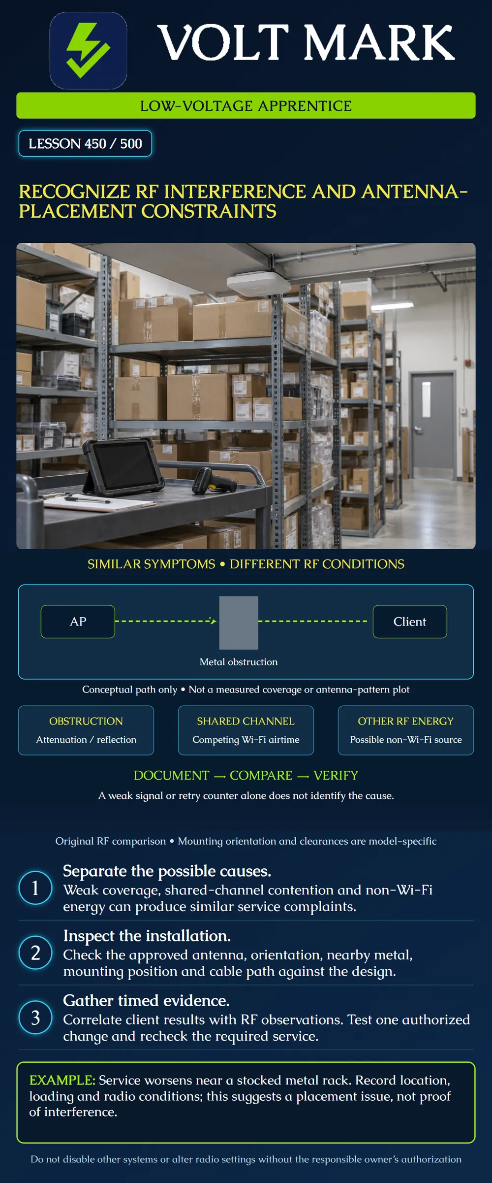
Recognize several RF conditions that can cause similar complaints and document antenna-placement constraints before recommending a change.
The poster is a conceptual Wi-Fi investigation example. It is not a measured propagation model, antenna pattern or instruction to modify a live radio system. Use the approved design, exact product instructions and authorized test plan. Antenna orientation, separation, environmental limits and permitted combinations are equipment-specific.
Cisco's Catalyst 9120 deployment guide describes how nearby metal and mounting orientation can alter coverage for the products it addresses. This is evidence that physical installation matters, not a universal rule that all access points need identical orientation or clearance.
HPE Aruba's WLAN alert documentation distinguishes Wi-Fi-related conditions and non-Wi-Fi interference observations. An alert is a useful investigation input; its label does not by itself identify a physical device or prove the cause of a particular user's failure.
An obstruction can attenuate or redirect the wanted signal. The poster's metal object represents that possibility. Its dashed line is a conceptual path, not a prediction of how much energy penetrates or reflects.
Devices using the same Wi-Fi channel can compete for airtime. Such contention is not identical to an unrelated non-Wi-Fi transmitter adding energy in the band. These conditions can coexist with weak coverage. A symptom such as retries or low throughput does not uniquely identify any one of them.
A busy application path may also have a non-radio cause. Preserve the distinction between observation, hypothesis and confirmation. Do not declare “interference” whenever an internet test runs slowly.
Record access-point model, antenna model or integrated-antenna variant, intended band, orientation and mounting position. Identify the approved drawing and manual revision. A directional antenna's intended coverage depends on where it faces and its documented pattern; an omnidirectional label does not mean equal radiation in every three-dimensional direction.
Observe nearby racks, ducts, structural metal and other relevant objects. Record conditions rather than inventing a universal clearance. A layout that works in an empty warehouse may behave differently after storage changes. Repeated observations under documented loading conditions are more useful than guessing from a single photograph.
For an external antenna, verify approved band, connector and cable arrangement, including the required port mapping. Connector fit alone does not establish an approved antenna. Feeder length and losses belong in the design record. Do not add an arbitrary extension or substitute a higher-gain antenna as an informal fix.
Record where and when the complaint occurs, which client/application is involved, and the band/channel and relevant operating state. Preserve the survey reference from lesson 449. Include the observation period and what the tools actually measured.
An SSID list is not a complete spectrum record. Wi-Fi observation tools and spectrum-analysis tools answer different questions; use suitable equipment and qualified interpretation. A classification or utilization reading should be correlated with client evidence and the physical situation.
Do not switch off a neighboring device merely because its location looks suspicious. Obtain the responsible owner's cooperation for any controlled test. Do not use jamming, forced disconnects or unauthorized captures as apprentice troubleshooting methods.
A fictional scanner works at point A before stock is loaded into a metal rack. Later, the same service is unreliable near that rack. Record a hypothesis: the changed physical environment may affect the radio path. Do not write: “the rack creates non-Wi-Fi interference.” Passive metal is not itself proof of a transmitting interference source.
The follow-up plan compares the same client and approved workflow at the same points, documenting inventory state and radio conditions. Concurrent changes in channel use, network traffic or client configuration must be considered. A repeated association between loading and degradation strengthens the placement hypothesis but does not justify inventing an attenuation value.
If an authorized design change moves or reorients equipment, record the new geometry and test the required area again. Check for new coverage gaps or unintended effects nearby. Do not accept a change solely because one test point improves.
An application complaint appears during a particular operating interval. RF observations also show increased non-Wi-Fi energy in that interval. That correlation warrants investigation, but it does not yet establish the emitting device or prove causation. Preserve timestamps and compare other intervals. A responsible specialist can plan a controlled test with the equipment owner.
If service improves while an unrelated wired-path problem is repaired, update the diagnosis. Do not retain an earlier RF explanation just because the original graph looked persuasive.
Use a short evidence table: Observed symptom and affected service. Exact location and period. Client, radio band/channel and tool. Physical installation and changed conditions. RF observations with their limitations. Hypothesis and plausible alternatives. Next authorized comparison. After-change verification and unresolved areas.
A useful finding says what the evidence supports and what remains uncertain. “Signal changed at three locations after an approved antenna relocation” is more defensible than “all interference fixed,” especially when no spectrum result or full service check exists.
Cisco Catalyst 9120 Access Point Deployment Guide: https://www.cisco.com/c/en/us/products/collateral/wireless/catalyst-9100ax-access-points/guide-c07-742311.html Opened directly. Used for physical-placement and orientation examples; the page includes a product lifecycle notice. No purchase recommendation or current universal mounting specification is inferred.
HPE Aruba Networking, WLAN Alerts: https://developer.arubanetworks.com/new-central/docs/wlan-alerts Opened directly. Used for the distinction between documented RF alert categories; no alert threshold copied as a universal limit. Sources checked 2026-10-01. Diagram and scenarios are original instructional synthesis.
A paper log shows scanner failures after a metal rack was filled. The observer labels this "non-Wi-Fi transmitter found." That conclusion exceeds the evidence: the changed rack may alter propagation, but no emitter has been identified. Revise the entry to "service degraded near the loaded rack; changed propagation is a hypothesis." Plan a same-client, same-location comparison with inventory state, channel conditions and application behavior recorded. Retain other plausible causes until authorized evidence distinguishes them.
Mistake: Treating a metal obstruction as proof of an interfering transmitter. Correction: Record the physical change as a possible propagation influence and separately investigate evidence of emitted RF energy.
Mistake: Identifying a physical device solely from an interference-alert label. Correction: Correlate the time and location with suitable RF evidence and an authorized controlled comparison before assigning a cause.
Mistake: Installing a higher-gain antenna because its connector fits. Correction: Verify the approved antenna, band, port arrangement, orientation and feeder requirements with the responsible designer before substitution.
Texas journeyman, 15 questions, scored by topic against the 70% mark. No card, and no account needed to start.
Free study material for low-voltage apprentices. This is a national foundation course: requirements differ by state and by local jurisdiction, and a practice that is common in one place is not a rule everywhere. Nothing here is a licence, a certification, or authority to work unsupervised, and completing it does not count as apprenticeship hours or continuing-education credit. Check the codes adopted where you are working, the licensing authority for that work, and your employer's safety programme. VoltMark is not affiliated with, endorsed by, or sponsored by NFPA, OSHA, NICET, BICSI, FOA, or any state or local licensing authority.

Electrician licensing exam prep: practice questions, timed exam simulations, and step-by-step help finding every answer in the NEC.