Compare a point-to-point radio link and a fiber route using the same stated service requirement, while identifying the different evidence each design needs.
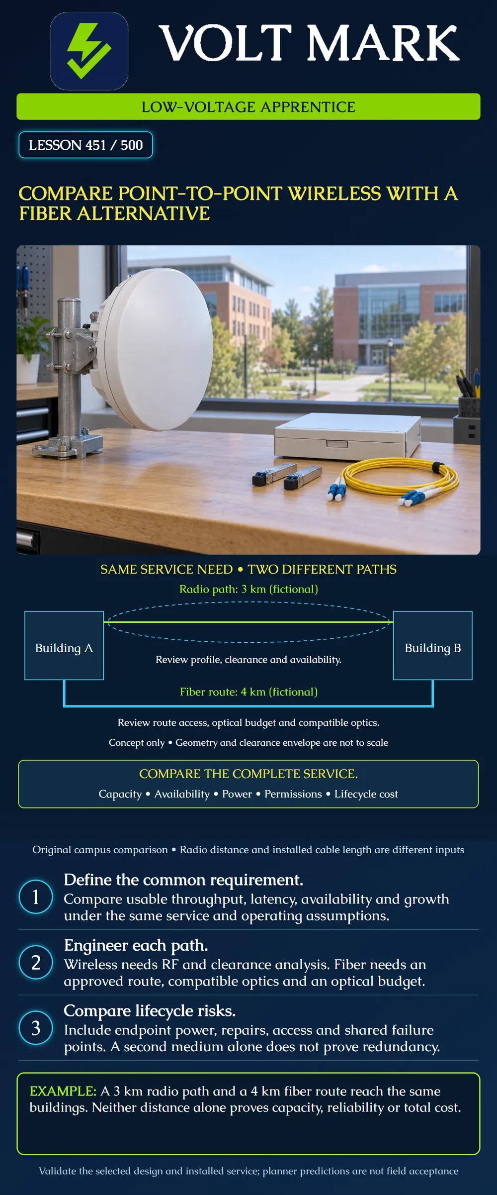
The campus drawing uses fictional distances: three kilometers between radio endpoints and four kilometers of routed fiber. Its geometry and clearance envelope are not to scale. It is not a design for a real property. Links from short campus runs to fifteen miles or more require equipment- and site-specific engineering; the medium name does not establish reach or performance.
Cambium LINKPlanner's profile documentation includes terrain, clutter, obstructions, Fresnel-zone visualization and antenna geometry. It demonstrates why seeing the opposite building is insufficient evidence for a high-availability radio design. A planning result depends on its inputs and assumptions.
The Fiber Optic Association describes optical links as compatible transceivers plus a cable plant. Fiber length, connections, splices, attenuation and bandwidth constrain the link. Receiver sensitivity and overload limits matter; a favorable loss calculation alone does not establish every performance requirement.
Write the intended traffic, usable capacity in each direction, delay tolerance, required availability, growth and operational support. State how capacity is measured and whether a quoted rate is aggregate, one-directional or simultaneous bidirectional service.
For a fictional planning worksheet, name the requirement R01: carry the owner's declared campus traffic between building switches under the approved load profile. The exercise does not assign a product or guaranteed rate. Leave a blank requirement marked unresolved rather than filling it with an attractive brochure maximum.
Compare like quantities. A radio physical-layer or aggregate headline rate should not be treated as equal to measured application throughput. A fiber interface rate also does not eliminate switching, oversubscription or application limitations elsewhere in the path.
Identify endpoints, mounting locations, path profile and obstructions. Record the intended frequency band, equipment, antennas, geometry and applicable operating authorization. Evaluate clearance using the approved engineering method, including relevant terrain and environmental assumptions.
Obtain predicted performance at the required operating mode and availability, not simply the highest mode the radio can occasionally reach. Interference, weather and propagation effects depend on the chosen band and site. Do not assert that every wireless link has the same rain sensitivity or that all bands require the same clearance prescription.
Plan mounting access, structural review where needed, power, surge/lightning measures and maintenance responsibilities. Avoid treating “no trench” as “no installation work.” Regulatory obligations are examined further in lesson 452; this lesson does not declare a frequency or radio installation automatically authorized.
Survey an approved physical route rather than substituting straight-line building separation. Include actual slack, entries, patching and other segments in the documented design length. Verify route access and permissions before assuming existing conduit or poles are available.
Match the optical modules, fiber type, wavelength arrangement, connectors, polarity and host support. Check the optical loss budget and the receiver's operating range, along with the permitted reach and bandwidth of the selected interface. Record required margin and acceptance limits from the design, not an invented universal allowance.
The glass signal path is not exposed to radio-frequency interference in the same manner as the wireless hop. That does not make the entire system immune to power failures, damaged cable, water intrusion into unsuitable components or equipment faults. Metallic cable components and building entries still require the appropriate design treatment.
The radio path is three kilometers. The fictional usable cable route is four kilometers because it follows the available path. The extra kilometer is a routing fact for the exercise, not a general fiber penalty.
The diagram's dashed oval merely calls attention to clearance analysis. It is not a calculated Fresnel radius, a guaranteed unobstructed area or a permitted antenna height. The lower blue route likewise does not prescribe burial depth, conduit size or an actual civil route.
The apprentice's job is to keep these inputs separate and traceable. Entering the radio distance as the cable length would understate this example's fiber route. Entering the routed fiber distance as the actual radio hop would misrepresent its geometry.
Use a common evaluation period and list assumptions. Include design, permissions, installation, endpoint equipment, power backup, inspections, support and likely repair arrangements. Record vendor quotations and exclusions when available; this exercise supplies no invented prices.
For radio, access to a roof or mast may control repair time. For fiber, the ability to locate and repair a damaged route may dominate an outage. Both need a plan for spare equipment, fault isolation and responsible responders.
Consider schedule constraints separately from long-term performance. A quicker initial installation does not automatically satisfy the required availability. A more expensive route does not automatically provide better service if its equipment or maintenance plan is unsuitable.
A radio backup and a fiber primary can provide useful diversity, but they may share endpoint switches, power supplies, building entries or upstream routes. Draw those common elements. A second medium does not remove a shared failed switch.
Define failover behavior, capacity during failure, detection, restoration and the authorized test. If the backup cannot carry the required critical traffic, document that limitation before calling the design redundant.
Prepare columns for service requirement, radio evidence, fiber evidence, unresolved item and owner. A radio planner predicts adequate capacity, but the obstruction survey is unverified: keep radio feasibility conditional. A fiber estimate fits the loss budget, but a route segment lacks access permission: keep construction feasibility conditional. Both alternatives have plausible technical designs, but neither includes backup power: leave availability acceptance unresolved. A hybrid drawing shows a shared switch: record the common failure point. After installation, use the approved acceptance plan to verify the actual service and retain evidence. Do not relabel a prediction as an as-built test.
Cambium LINKPlanner, Profile: https://lp.cambiumnetworks.com/doc/profile.html Opened directly. Used for path-profile and clearance-planning concepts; model-specific numerical availability/clearance guidance not generalized.
The Fiber Optic Association, Fiber Optic Data Links: https://thefoa.org/tech/ref/appln/datalink.html Opened directly. Used for transceiver/cable-plant compatibility and optical operating constraints; no universal reach or margin assumed. Sources checked 2026-10-01. Campus distances, diagram and review scenarios are original.
The paper estimate uses 3 km for both options. The approved cable route is actually 4 km, so the fiber estimate omits 1 km before any separately specified slack or entries. Correct that input and obtain a revised optical and cost assessment. The radio estimate still needs its 3 km path profile checked for obstructions and clearance. If both links share one endpoint switch, record that common failure point rather than claiming independent service merely because the media differ.
Mistake: Using building separation as installed fiber length. Correction: Trace the permitted route and its additional segments; keep the route length separate from the radio-hop geometry.
Mistake: Comparing a radio headline rate with a fiber service requirement. Correction: Compare usable traffic capacity under the same direction, load and availability assumptions, with supporting design evidence.
Mistake: Calling radio backup independent while it shares the primary link's switch and power. Correction: Draw the common dependencies and specify what failures the backup can actually survive.
Texas journeyman, 15 questions, scored by topic against the 70% mark. No card, and no account needed to start.
Free study material for low-voltage apprentices. This is a national foundation course: requirements differ by state and by local jurisdiction, and a practice that is common in one place is not a rule everywhere. Nothing here is a licence, a certification, or authority to work unsupervised, and completing it does not count as apprenticeship hours or continuing-education credit. Check the codes adopted where you are working, the licensing authority for that work, and your employer's safety programme. VoltMark is not affiliated with, endorsed by, or sponsored by NFPA, OSHA, NICET, BICSI, FOA, or any state or local licensing authority.

Electrician licensing exam prep: practice questions, timed exam simulations, and step-by-step help finding every answer in the NEC.