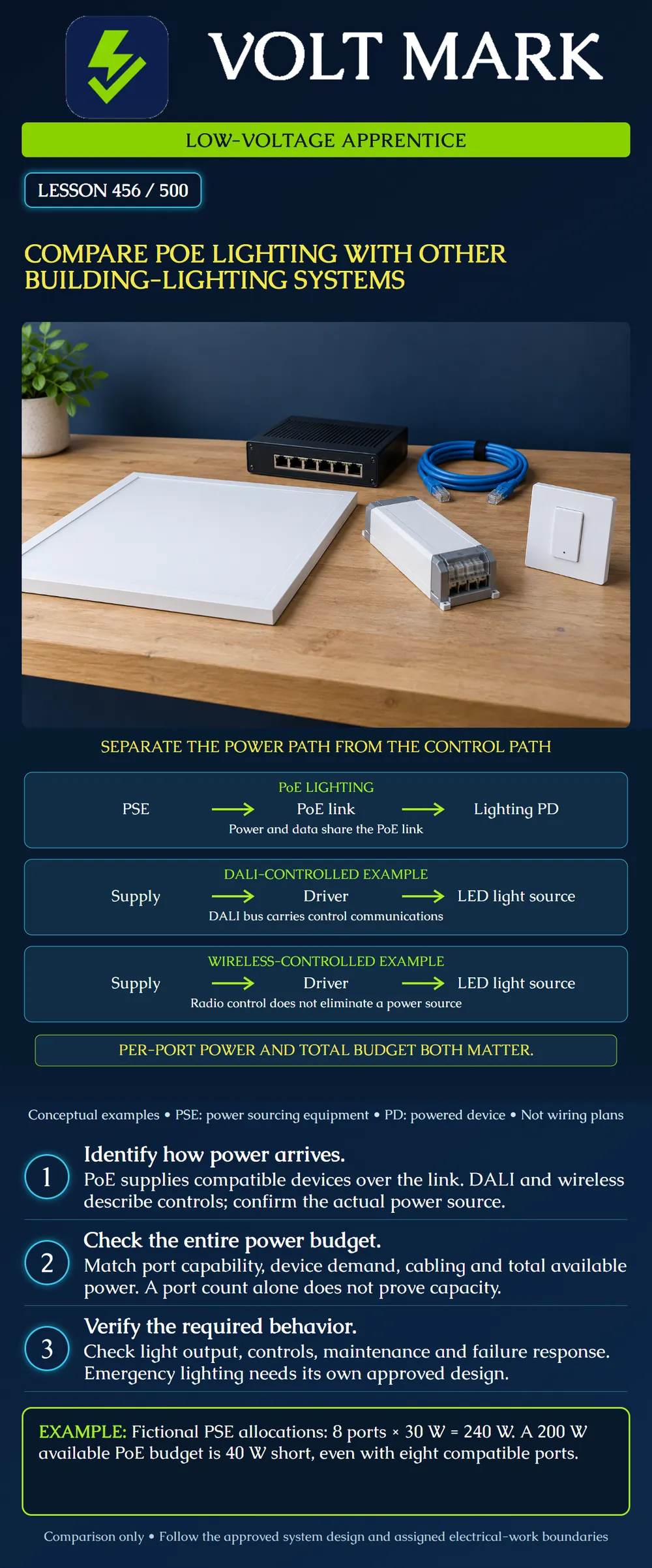
Separate the power-delivery path from the control path in lighting architectures. Compare a PoE lighting endpoint with separately powered LED drivers controlled through DALI or wireless commands. Check an illustrative shared power budget without treating it as a complete design.
This lesson remains within low-voltage systems education. Other lighting power arrangements are shown only to explain interfaces and dependencies. It does not authorize branch-circuit wiring, work inside energized equipment or selection of an emergency-lighting system. Use the approved design, listed equipment instructions and assigned qualified supervision.
A light source needs energy even when its controls communicate wirelessly. Start every comparison by identifying the source, conversion equipment and path to the light. Then trace the control command separately.
PoE means Power over Ethernet. PSE means power sourcing equipment; PD means powered device. The PoE link carries power to a compatible endpoint as well as Ethernet data. A lighting endpoint may incorporate conversion and control electronics. Confirm the approved architecture rather than assuming the Ethernet cable connects directly to bare LEDs.
The Ethernet Alliance distinguishes available power at the source from power at the receiving device. For example, its IEEE 802.3bt overview gives upper figures of 90 W at the PSE and 71.3 W at the PD. These describe different interfaces and do not mean every PoE port supplies those values. Match the actual power class and equipment. [1]
In the DALI example, the supply feeds an LED driver, and that driver powers the light source. The DALI control bus conveys commands and supports the control system. Its bus supply is not a replacement for the luminaire's operating power source. DALI systems include control gear and control devices, which can include application controllers and input devices. [2]
The wireless example makes the same distinction using a radio control path. A wireless command does not establish whether a fixture uses a branch-circuit supply, a remote DC supply or another approved arrangement. Read the actual system documents. Do not infer electrical safety or wiring classification from the communication method.
The poster compares illustrative architectures, not mutually exclusive product categories. An approved system can combine technologies through suitable interfaces. The objective is to label power and control accurately, not declare one technology best for every building.
Use a fictional PSE with eight compatible ports. The exercise requires an allocation of 30 W at the PSE for each port. Total required allocation is 8 × 30 W = 240 W. If the available PoE output budget is 200 W, the allocation exceeds that budget by 40 W.
These values are explicitly PSE-side allocation figures. They are not eight 30 W lamp ratings, and they do not imply that 30 W arrives at every lamp. Cable losses and endpoint conversion separate those boundaries. The example also does not assume a particular switch's allocation algorithm.
A six-port allocation at 30 W each would total 180 W, leaving 20 W within the same fictional 200 W budget. That arithmetic does not prove the six-device design is acceptable: verify individual port support, other loads, configured limits, cabling, equipment operation and project requirements. Do not infer adequate illumination from an electrical power total.
Prepare a worksheet with the same questions for each candidate architecture. What light output and control functions are required? What equipment powers each endpoint? Which shared components can affect multiple rooms? What must happen when a controller, network connection or power source is unavailable? Who can maintain the system and how are replacements verified?
A working dim command proves only the observed control action. It does not establish required illumination, color quality, occupancy behavior, emergency performance or long-term reliability. Record each specified function separately.
In a classroom example, system A uses centrally supplied PoE lighting while system B uses local drivers and a separate control bus. A loss of one central component could affect several endpoints in A. B can also have shared control dependencies. Neither description alone establishes superior availability; draw the actual dependencies and evaluate the required failure scenarios.
Use the installation design to confirm cable type, route, environmental suitability, connections and relevant thermal constraints. A cable that carries data successfully has not thereby demonstrated every required power-delivery condition. Refer unexplained performance or heating concerns to the qualified lead; do not improvise substitutions.
Handover should identify approved components, endpoints, configuration ownership, test results and maintenance responsibilities. Keep data-network administration and electrical work assignments explicit. A technician's familiarity with Ethernet does not automatically qualify them for every electrical task inside a PoE power supply or other lighting equipment.
An ordinary lighting system does not become an approved emergency system merely because someone connects its power source to a UPS. The responsible designer must establish the applicable equipment, transfer behavior, duration, controls, wiring and testing requirements for the intended use. This lesson supplies no universal emergency duration or state-specific rule.
Record emergency functionality as unresolved until the approved project documents establish it. Do not invent a bypass or override for a classroom illustration. The poster's reminder is a boundary on this comparison, not a complete emergency-lighting design procedure.
Draw a power path and a control path for each poster example. Mark conversion equipment and shared dependencies. For a fictional 200 W available PSE budget, calculate eight allocations of 30 W each. State both the result and why lamp wattage cannot simply be substituted for the stated PSE allocation.
Answer: No. Identify its actual power arrangement.
Answer: No; distinguish control-bus power from lamp operating power.
Answer: 240 W, exceeding a 200 W available budget by 40 W.
Answer: No. Check per-port and aggregate constraints.
Answer: No. The complete approved design and applicable requirements must be established.
[1] Ethernet Alliance / Sifos Technologies, PD Design for Conformance and Interoperability overview: https://ethernetalliance.org/blog/2022/10/17/ethernet-alliance-poe-blog-sifos-app-note/ Opened October 1, 2026. Supports PSE/PD boundary and interoperability concepts. This lesson does not adopt the page's imprecise early-generation pair wording or present it as the full IEEE standard. [2] DALI Alliance, DALI systems: https://www.dali-alliance.org/dali/systems.html Opened October 1, 2026. Supports control gear, control devices and control-bus distinctions. Not a project wiring or safety-classification determination.
Original conceptual diagrams, comparisons and arithmetic exercises. 8×30=240; 240−200=40; 6×30=180; 200−180=20, all watts at the stated PSE allocation boundary.
The fictional switch offers a 200 W PoE output budget. Eight ports each require a 30 W PSE-side allocation, so 8 x 30 = 240 W and 240 - 200 = 40 W is unfunded. Mark the shared budget insufficient even if every individual port supports 30 W. Six such allocations would total 180 W and leave 20 W, but require separate approval of endpoint support and the complete lighting design; reducing the arithmetic load alone does not verify the intended illumination.
Mistake: Using lamp wattage in a PSE allocation calculation without checking the boundary. Correction: Use the documented source-side allocation for the shared budget and account for cable and endpoint conversion when relating it to the light source.
Mistake: Treating a working DALI command as proof that the control bus supplies lamp energy. Correction: Trace the driver power supply and control bus separately, using the actual architecture.
Mistake: Calling PoE lighting emergency lighting because the switch has a UPS. Correction: Refer the full emergency function, equipment, controls and testing requirements to the responsible designer.
Texas journeyman, 15 questions, scored by topic against the 70% mark. No card, and no account needed to start.
Free study material for low-voltage apprentices. This is a national foundation course: requirements differ by state and by local jurisdiction, and a practice that is common in one place is not a rule everywhere. Nothing here is a licence, a certification, or authority to work unsupervised, and completing it does not count as apprenticeship hours or continuing-education credit. Check the codes adopted where you are working, the licensing authority for that work, and your employer's safety programme. VoltMark is not affiliated with, endorsed by, or sponsored by NFPA, OSHA, NICET, BICSI, FOA, or any state or local licensing authority.

Electrician licensing exam prep: practice questions, timed exam simulations, and step-by-step help finding every answer in the NEC.