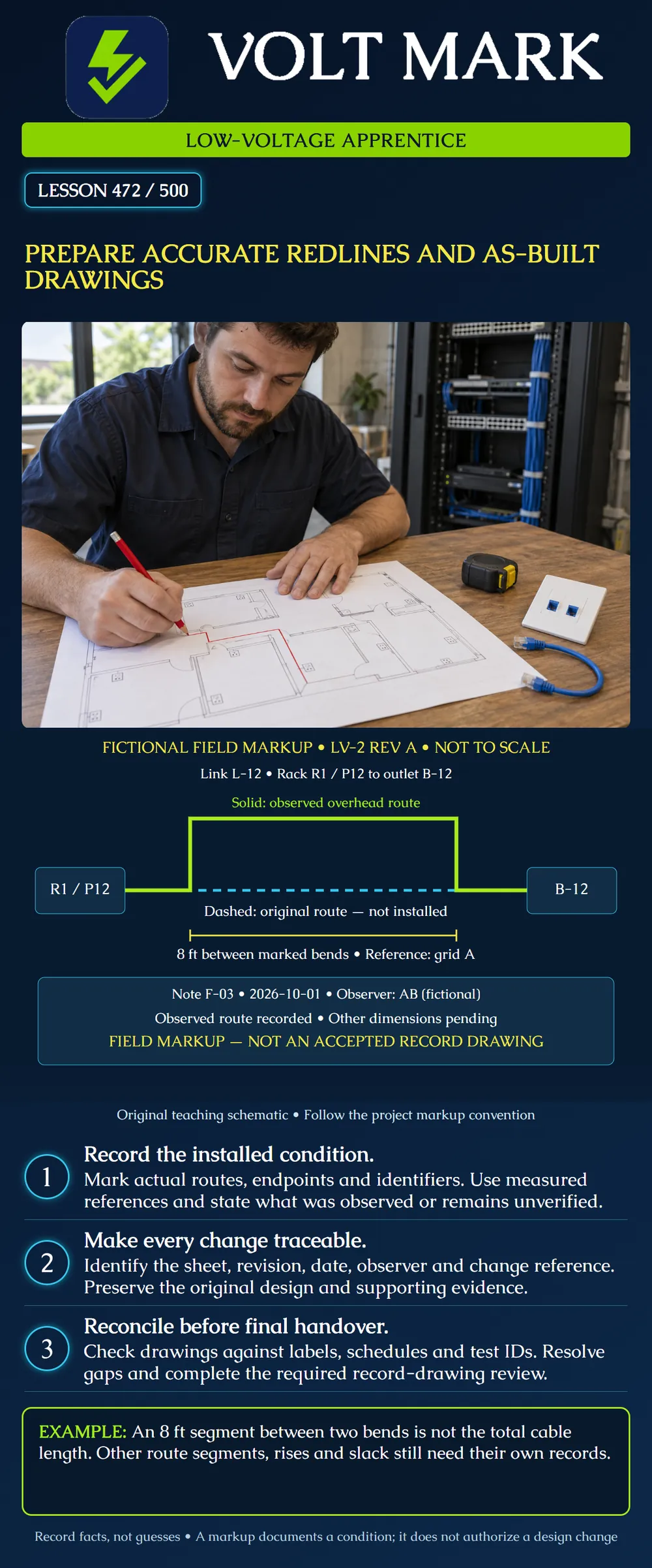
Record low-voltage installation changes in a traceable field markup and explain what remains before that information can become a reviewed record drawing.
The poster is fictional field note F-03 on sheet LV-2 revision A. It illustrates documentation, not an approved route design or complete construction drawing. The observed route, identifiers and measurement are classroom data. Actual drawing conventions, responsibilities and deliverables come from the project requirements.
UFGS 01 78 00, August 2026, describes as-built drawings as contractor-maintained markups showing actual conditions and deviations. It describes record drawings as the final compilation of those conditions. The guide specification is intended to be tailored to a project. [1] These definitions are useful examples, not a mandate that every U.S. owner use identical terminology or submission procedures.
A working markup may contain open questions. A polished electronic drawing can still be wrong. Neither appearance nor filename establishes that its contents have been verified or accepted.
Use the project's names for working redlines, as-built records and final record drawings. Identify status explicitly so a maintenance technician does not mistake a preliminary sketch for a completed installation record.
The fictional link is L-12, from rack R1 patch-panel position P12 to outlet B-12. The dashed cyan path represents the original route that was not installed. The solid lime path represents the observed overhead route.
The schematic is not to scale. Its colors serve the VoltMark teaching palette; line styles and written labels also identify the routes. On a real project, follow the required redline colors, layers and symbols rather than copying the poster colors.
Field note F-03 is dated 2026-10-01 and attributed to fictional observer AB. It records an eight-foot horizontal segment between the indicated bends. Other dimensions remain pending. Therefore the note is an incomplete field markup, not an accepted record drawing.
The poster names grid A as a reference for the measurement but does not draw a complete coordinate system or locate every bend. A production drawing needs enough referenced dimensions to locate the route without guessing. The exercise intentionally exposes that remaining task.
Use stable, identified project references such as approved grids or established building features. State units and what the measurement represents. A distance between bends is different from elevation above finished floor, offset from a wall or installed cable length.
Do not infer dimensions from this poster's pixels. Eight feet is the stated length of one segment, not the sum of the route. The remaining segments, vertical transitions and slack are not supplied, so no total cable length can be calculated.
Record the relevant location and elevation information before concealment when permitted and practical. If a section is inaccessible or unobserved, label its status and seek the required verification. Do not convert an assumption into a measured fact.
For campus fiber, the same discipline applies to route sections, structures, cable identifiers and termination locations. A sketch without adequate location references should not be treated as an excavation clearance or proof that no other utilities are present.
Link L-12 should refer to the same link in the drawing, cable label, panel schedule, outlet schedule and test-result package. Rack R1/P12 and outlet B-12 are endpoint references, not interchangeable names for every nearby device.
If a label changes, update the related records through the project's controlled process. Preserve the relationship between old and new identifiers where needed so earlier test evidence remains traceable.
Do not silently attach a passing test from a different link because its filename looks similar. Resolve discrepancies before treating the package as complete. Drawing accuracy includes the logical connection between records, not just the geometry of lines.
Identify the drawing sheet and revision that was marked, the date, the person recording the observation and the supporting field note or change reference. Attach approved photographs or other evidence with enough context to identify their location.
The fictional note establishes what the exercise says was observed. It does not show a design-change approval. A record of an installed deviation and authorization for that deviation are separate matters.
If a field condition differs from the authorized design, report it through the responsible project roles. Do not use a redline to quietly approve your own route substitution or to hide an unresolved technical issue.
Compare the marked route with related plans, risers, schedules and details. Confirm that both endpoints exist under the recorded names and that any changed penetration, pathway or equipment reference is carried to the relevant documents.
Check the markup for conflicting notes. If one sheet identifies outlet B-12 while a schedule identifies B-21, resolve the discrepancy rather than choosing the version that is easier to edit. Keep unresolved questions visible until evidence supports the correction.
Use legible annotations that distinguish removals, additions and explanatory notes. The project may require revision clouds, specific layers or an issue log. Follow that convention and preserve superseded versions according to its record process.
Transfer verified information into the required final format through the assigned drawing role. Confirm the required review, file naming, linked references and delivery package. Do not call it accepted merely because a PDF was exported or copied to a folder.
The final record should accurately communicate the installed condition within its stated scope. It should not claim measurements, inspection, technical compliance or acceptance that have not occurred. Keep required technical review separate from administrative receipt of files.
For F-03, the next action is to obtain the missing route dimensions and sufficient location/elevation references, reconcile identifiers and supporting records, and complete the project's review. The exercise cannot be finalized by simply deleting the word “pending.”
Recreate F-03 with distinct original and observed routes. List the missing measurements and records needed to locate the installation. Add an unresolved-item log rather than inventing those values. Explain how you would match L-12 to its test report and endpoint labels.
Answer: No; the legend identifies it as the original route not installed.
Answer: No; only one segment is dimensioned.
Answer: No.
Answer: No.
Answer: Identify them as unresolved and obtain appropriate evidence rather than guessing.
[1] UFGS 01 78 00, Closeout Submittals, August 2026, sections 1.2.1 and 1.2.2 and project-tailoring note: https://www.wbdg.org/FFC/DOD/UFGS/UFGS%2001%2078%2000.pdf Opened October 1, 2026. Used for document-state definitions and project-specific tailoring only. Its federal guide-specification context is not presented as a universal local-code or contract requirement.
Original fictional diagram and field note. Only one eight-foot segment is supplied; no total-length calculation is supported.
F-03 identifies L-12 between R1/P12 and B-12 and gives one eight-foot segment on the observed route. A reviewer cannot calculate total cable length or locate every bend from that one dimension. Keep the original route marked not installed, list missing dimensions and elevation references, and reconcile the ID with the test package. A clean drawing export would still be incomplete until those observations and the required review are supplied.
Mistake: Treating the eight-foot segment as total installed cable length. Correction: Identify which segment was measured and leave all unmeasured route portions unresolved until verified.
Mistake: Using a redline as retroactive approval of a route substitution. Correction: Record the observed condition and separately refer the deviation through the authorized design-change process.
Mistake: Making the drawing look final by deleting pending dimensions. Correction: Obtain the missing evidence and document review status rather than concealing unverified geometry.
Texas journeyman, 15 questions, scored by topic against the 70% mark. No card, and no account needed to start.
Free study material for low-voltage apprentices. This is a national foundation course: requirements differ by state and by local jurisdiction, and a practice that is common in one place is not a rule everywhere. Nothing here is a licence, a certification, or authority to work unsupervised, and completing it does not count as apprenticeship hours or continuing-education credit. Check the codes adopted where you are working, the licensing authority for that work, and your employer's safety programme. VoltMark is not affiliated with, endorsed by, or sponsored by NFPA, OSHA, NICET, BICSI, FOA, or any state or local licensing authority.

Electrician licensing exam prep: practice questions, timed exam simulations, and step-by-step help finding every answer in the NEC.